
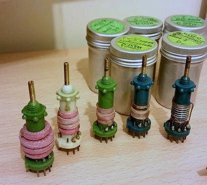
When I was a kid there were available ready-made coils for the hobbyist. Q-Max sold their business to DENCO (Clacton) in the early 60s, and I believe they stopped making them in the late 60s. Now these coils were fantastic. Denco produced RF antenna, oscillator and IF coils for superheterodyne receivers, covering 150kHz through to 31MHz. These coils formed the basis of many school and college training programs, in design, assembly and alignment of superhet receivers. They had ranges for valves (tubes) and transistors. The coils came in an aluminium tin, with a screw-top, that also doubled up as a screening container for the coils in use.Introduction
I could never afford them on my 2s/6d weekly pocket money (about $1), then when I started working in 1968 they were hard to get (and I only earned 35 shillings a week). By 1970 there were few places actually selling them. Today I can afford them, but there are just a couple of rare examples on e-bay at ridiculous prices. I have seen US$55 for just one receiver coil.
In this page I will show you that you can create similar coils, if you have access to a 3D printer. I have also taken the stage a little further. When I was a kid I would disassemble old radios and re-use the components. The old IF cans often had four thick wires to which the coils were terminated. This was great for rewinding, then adding components, such as tining capacitors, inside the screening can.
My coils are also a little thinner. The original Denco coils were 5/8" Diameter (15mm), which made them rather large. My coils are 9.9mm Diameter, and this will affect the number of turns, but not the turns ratios. My coils also have the legs 0.4" spacing, so that they fit into veroboard. I kept the plastic screw so that I can fit them to a hole in an aluminium chassis, when working with valves. I also added a knob, so that they can be finger-tuned, and no need for a trimming tool or screwdriver.
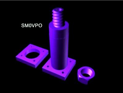
The formers were created using 3D-Studio Max 8, which is a professional 3D modelling and animation program. At the end of this section you will find a link to the .MAX file. The file was exported to ASCII format .STL and .OBJ files.
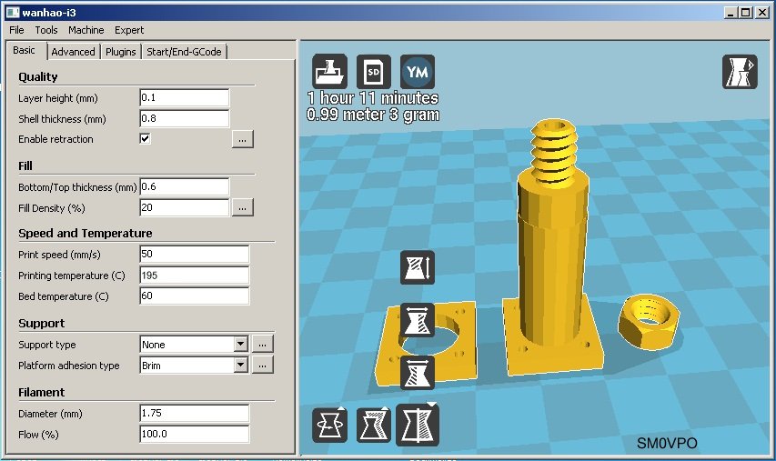
I then used used CURA to slice the 3D image into layers and create the .GCODE files needed by the 3D printer. The printer is a Wanhao Duplicator i3, using standard PLA filament. My .GCODE file also prints a "raft", upon which the former is printed. Printing is then very stable and adheres to the print bed very well. The down-side is that CURA puts an extra layer under the former, which looks a bit untidy, but this can be filed off with sandpaper. I didn't bother to correct it.
When the file was created in 3D-Max I did NOT "merge" the primitive objects, so the screw-thread, tube, cone and base are all separate objects. I did "connect" them so that they can be moved around the work area and still remaining aligned. I put a 2.5mm Diameter hole in the top screw-thread, using boolian subtraction, but I didn't bother to make a hole in the cone. My 2.5mm hole will guide a nice sharp 2.5mm drill bit so you can drill an accurate hole before using a 3mm tap to put the 3mm thread in the former, for the tuning screw. These are details you may need to know if you want to modify the files.
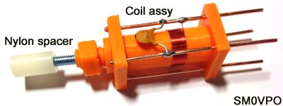
The complete coil former is made in three pieces:
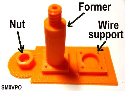
Assembly is very easy. Separate the components from the raft and push the upper wire support over the top of the former tube. It is a fairly tight fit, but I used a very small dab of super-glue (cyanoacrylate adhesive)to fix it in position. Before you glue it, place the former on a flat surface so that the base and the wire support are perfectly aligned. At this point you can put the nut on the screw-thread for safe keeping, and then drill and tap the hole for the 3mm tuning screw.
Wind the coils needed now, before you fit the component wires.
When the coil(s) have been wound, push four hard-drawn copper wires through the former holes. The wire must be 1mm Diameter, maximum. I did not need to drill the holes for the wire. If you need a suitable source of hard-drawn copper wire, then the centre-conductor from satellite TV cable is perfect. A very small dab of super-glue on the top support is all that is needed to secure the wires.
If you want to experiment with the windings, then you can of course fit only 2cm of wire, so that there is enough to terminate your windings, but allow coils to be re-wound.
Now you can solder the coils to the wires.
Finally, super-glue a 4mm Diameter, 10mm long ferrite slug to the end of a 30mm long M3 bolt. I filed most of the head off the bolt so that the ferrite can rise farther upp the former, is rough to take glue, and easier to hold in place while the glue sets. Insert the bolt with the ferrite into the bottom of the former and screw it into the coil former. When the ferrite enters the coil it is difficult to rotate, so I used a pencil with an eraser at the top to rotate the ferrite.
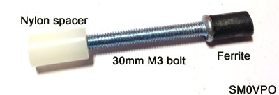
When the coil is complete I added a 3mm tapped nylon spacer to the end of the bolt as a knob. This I tacked in place with a micro-dab of glue, but this should be done after the former is mounted, if you are to mount it on a chassis using the plastic nut. The knob allows the tuning screw to be easily rotated. If you don't have access to these nylon spacers, then two nuts can be added and locked to act as a kind of knob.
In this example I wound a test coil for an RF course demonstration. 20 turns, 20pf = 20 metres, or 15 MHz. With the tuning ferrite slug 50% into the coil it was almost perfect; within 200 kHz :-)
Download the here:
denco_sub_01.max for 3D-Studio Max
denco_sub_01.stl for 3D STL image (ASCII format)
denco_sub_01.gcode for 3D printer
It is interesting that you can open the .STL and .GCODE files using notepad, if you really want to addle your brain with script and code :-) But don't go down that road. Value your sanity.
The original Denco information did not give any turns information at all, but the inductance was specified for each band. Since my formers are a little smaller in Diameter, I have done some calculation work on the turns needed using my formers. These values were calculated and tested using a 30pf to 365pf variable tuning capacitor.
| Range | Freq L | Freq H | uH | Turns | Notes |
|---|---|---|---|---|---|
| 1 | 150 kHz | 500 kHz | 2350 | 572.7 | 0.10mm Dia. Enamelled. 6 layers |
| 1osc | 615 kHz | 965 kHz | 573.2 | 282.75 | 0.10mm Dia. Enamelled. 3 layers |
| 2 | 515 kHz | 1.545 MHz | 271 | 194.50 | 0.15mm Dia. Enamelled. 3 layers |
| 2osc | 1.080 MHz | 2.010 MHz | 129 | 137.75 | 0.15mm Dia. Enamelled. 3 layers |
| 3 | 1.67 MHz | 5.3 MHz | 27.2 | 63.25 | 0.20mm Dia. Enamelled. 2 layers |
| 4 | 5.0 MHz | 15 MHz | 2.9 | 18.50 | 0.35mm Dia. Enamelled. 1 layer |
| 5 | 10.5 MHz | 31.5 MHz | 0.65 | 7.50 | 0.50mm Dia. Enamelled. 1 layer |
For ranges 1 and 2, the oscillator coils must be 465 kHz higher than the receive frequency, which is a large difference that cannot be compensated by tuning the inductor. The actual frequency range is quoted, along with the required (lower) inductance to get this frequency range. The oscillator coil will also require a larger padder capacitor, in parallel with the tuning capacitor, to set the upper frequency limit.
Note that only the tuned (resonant) winding is given. An antenna coupling winding for an RF coil will be about 5% to 10% of this value. As an oscillator in a self-oscillating mixer, then you will need about 15% for a transistor collector and 4% for the emitter winding. If you find any further data for the old Denco coils with the actual number of turns then please let me know.
I gave you the turns values from the calculation, so there are decimal values. Remember that the terminal posts are in increments of 0.25, 0.5 and 0.75 turns: it is not possible to have a whole turn, because two different post are needed to connect to the coil. This is not relevant for ranges 1, 2 and 3, but it can make a difference for ranges 4 and 5. When winding the coils, try to keep the actual winding below the centre of the winding area, try to keep it about 1/3 of the way up the former. This will allow some space to retract the tuning ferrite slug (upwards) and give you a wider tuning range.
The easiest way to make a nice neat coil is to cut a strip of masking tape, about 3mm wide and use this to trap the starting turn. The remaining turns can be wound over the tape. When you have the last turn, lift the tape and lay it back over the the last turn to secure it. I am a super-glue (crazy-glue) fanatic, so I used a little dab of super-glue to secure the first turn. When the last turn was in place I checked for no gaps, then put a very light smear of the glue around the coil. This method prevents loose turns and possible microphony, but it means a little bit more mucking about.
The coils should NEVER become longer than 10mm, unless you start the coil further down the former. To keep the coil to 10mm or less will give the ferrite tuning a wider range. To calculate the winding length, divide 10mm by the diameter of the enamelled wire you intend to use. If you use 0.25mm Diameter then you will have space for 40 turns in one layer. If you need more turns then wind back over the first 40 to make a two-turn coil. Unless you are dealing with high-power transmitting, then 0.1mm Diameter is adequate, and will allow you to have 100 turns in the 10mm.
There is no "grand unified formula" for coil winding. These two formulas are good for single layer or loadsa layers but you may just have to make a small correction. If you are still interesting in calculating your own coils, then the following calculators can be used for these formers. The following winding data is to be used:
| Parameter | Explanation |
|---|---|
| Inductance | This is the actual inductance you want, decimal values ae allowed |
| Length of winding | The total width of the winding (max 10mm) *1 |
| Former Radius | This is 5mm radius for my former (10mm diameter former) |
| Former Diameter | This is the former diameter (10mm for my former) |
| Winding depth | The diameter of the wire multiplied by the number of layers *2 |
Note *1 - Use 10mm, then if the resultant number of turns multiplied by wire diameter is less than 10mm then, re-calculate using the new, calculated coil length. For example, 30 turns of 0.2mm Dia. wire has a coil length of 30 x 0.2 = 6mm. Re-calculate using 6mm.
Note *2 - Assume the wire is square. If you have 10 layers of 0.2mm Dia. wire then the winding depth is 10 x 0.2 = 2mm. If you don't know how many layers there are then assume 2mm, calculate, then from the number of turns you can estimate the number of layers needed.
If you use large multi-layer coils then you will need some form of guide or support to either side of the coil itself. I used old credit-card or hotel door pass-key plastic.
Well I hope that you have learned something useful with this information. If you have any questions or comments then please use my forum to pose them. I often get overloaded with e-mail. Return to the INDEX page for the link to the forum.
Very best regards from Harry - SM0VPO
Return to INDEX page