
I have a lovely old and reliable Yaesu FT-101ZD. It is fantastic, but as always there is something preventing me using it in Sweden. In this case it is the bottom floor of an apartment block we have just moved into (again). I have no signals at all. Sorry!! ... I have S-9 noise from Switch-Mode PSUs, TVs, central-heating, fans, economy lighting, and I am 100% sure that the birds nesting under the bedroom window ledge are contributing something!
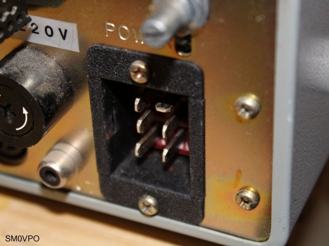
What I want is to achieve reliable portable operation that I can set up in a couple of minutes in my lunch break. I want to get away from the housing estate and run the radio from my car. I have a 12V inverter option fitted to the FT-101ZD, but it needs a 6-pin Cinch-Jones type power plug, with one horisontal pin. They are not very common, in fact the only GOOGLE pictures I can find are from messageboards where people are crying out for them.
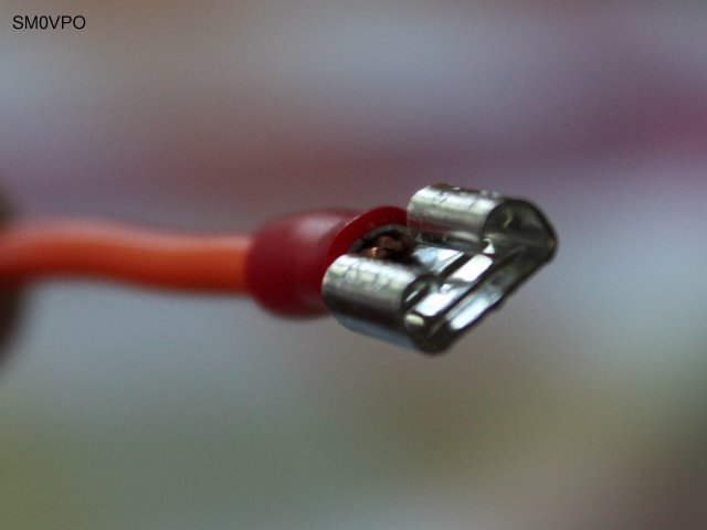
BUT ... I have a 3D printer, and automobile "spade connectors" will fit the chassis-mounted Cinch-Jones plug in the back of the radio. Now I can do something nice. May not be pretty, but at least I can overcome the problem (ツ)
Looking at the FT-101ZD circus-diagramus-confusicus I see that the two centre pins of the plug are not used. Only the top two and the bottom two pins; pins 1, 2, 5 and 6. The top and bottom right-hand pins (1 and 5) are a simple link for the 6146 valve/tube heaters - series = 12 V. Top-left (2) is the power negative, and the bottom-left is the positive terminal.
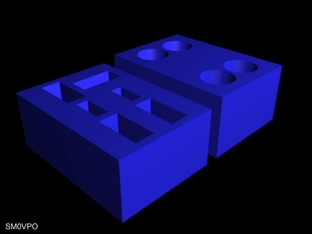
This is ridiculously easy. It is just two blocks of plastic, 12mm x 25mm, and each is just 10.5mm thick. The upper portion has four holes for the cables. The lower block has four large holes 3mm x 7.5mm for the corner connectors, and two centre holes 4.5mm x 2mm for the two unused centre pins of the chassis socket. I wanted two plastic lumps that are a tight fit over and under the spade terminals, thus keeping them captive between the two blocks. I made the holes exactly the correct size so the 3D printer will make them about 0.05mm too small. This will make the whole assembly solid and ridgid, and the two cheeks need to be pressed together in a vice. I then run a small dab of super-glue (cyanoacrylate) in the crack to seal it. The 3D modelling tool I use is 3D Studio Max 8. Here is the project rendered in my 3D program:
If you want the files then here they are all here. I also exported the project to .STL, and if you use a WANHAO Duplicator i3 (copy of Prusa Duplicator i3) then here is also the .GCODE file. The .GCODE is pretty generic so it should work on most 3D printers using PLA filment. Right-click on the files and select "Save as". The STL and GCODE files are in ASCII so some web browsers will open and display them as text.
jones-plug_6.max 3D Studio Max file.
jones-plug_6.stl .STL file.
jones-plug_6.gcode .GCODE file.
My printer settings are:
The printer temperature is 200°C, which is 5°C hotter than recommended for PLA filament. I find that I get a better print at 200°C. I also turned the fill density down to 20% so that the connector inserts will just bend/compress the plastic a little without rupturing and weakening the assembly.
To assemble, just pass the cables through the top part of the assembly before you crimp the connectors. Before crimping the connectors are just a firm fit in the housing, but crimping deforms the 6mm Dia. shank of the connector. Use a vise to press the two halves together to sandwich the connectors. Then run a LITTLE super-glue in the crack between the two blocks.
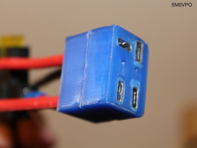
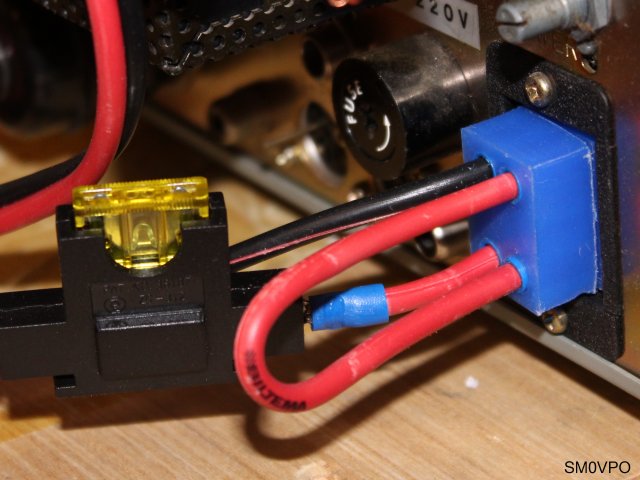
There you have it!! One 6-pole Jones connector suitable for use with the Yaesu FT-101ZD. It may be a bit stiff to fit to the FT-101ZD, but a flat-blade screwdriver can be used to open up the connectors so that it firmly in the radio plug. Do not force it. Mine sits in place snugly and comfortably, with no connector "Play" (glapp/glitches). I have to rock it a little when removing it, but since it is to carry 20 Amperes at 13 V DC so it is good to have a nice secure contact.
The other ends of the cables are fitted with huge crocodile/aligator clips. It is ok, but it opens the possibiity of accidentally connecting to the battery poles the wrong way around. I have a 67-year old brain, so I may put an "idiot-diode" and a 12 V car relay in there. No diode voltage drop and relay does not kick in if the polarity is reversed. 67-year old brain proof :-)
I have ordered a 5.2m stainless-steel telescopic whip antenna, and my next job will be to use a galvanised umbrella stand and a 3D insulator to support the whip. Then I can start operating from Rosersberg during my lunch breaks. I cannot use the telescopic antenna I made with aluminium tubes because I do not want to scratch my brand-new car to hell (it has really rough metal edges).
If you are interested, the 5m long telecopic whip is available from MFJ enterprises (http://www.mfjenterprises.com) but don't rush out and buy one yet. I ordered mine a few weeks ago and the order is on hold; "Your Order Status is (Backorder)" for four more weeks. Obviously none in stock. Perhaps this is an opportunity to try my 20m loop antenna?
I hope that someone can possibly use this information. I know there are several people desperately seeking a 6-Pole Jones connector for the Yaesu FT-101ZD.
Dont forget to visit my messageboard if you have any questions about this or any other project. I always look forward to receiving feedback, positive or negative.
Very best regards from Harry Lythall
SM0VPO (QRA = JO89WO), Märsta, Sweden.
EA/SM0VPO (QRA = IM86BS), Nerja, Spain.