It is based on a circuit sighted in Ref 1.
I have called it a Pocket Metal Detector as it is fully self contained and should fit the "larger" pocket.
The circuit shown (Fig 1) is of a metal detector of simple design and intended to fit within a CD "jewel" case.
It is based on a circuit sighted in Ref 1.
I have called it a Pocket Metal Detector as it is fully self contained and should fit the "larger" pocket.
As with most metal detectors; this design works on the principle of detecting the difference (or beat note) obtained by the mixing of two oscillators, the frequency of one which can be caused to alter, when the presence of a metal object is near its "search-coil" which is one of the frequency determining elements, of one of the oscillators.
The other is a fixed or reference oscillator (400KHz).
The circuit uses two CMOS IC’s
IC1 uses inverters connected as a Colpitts oscillator of 100KHz; the LC frequency determining elements being the search coil and parallel resonating capacitor.
An 80 turn close wound 30swg 100mm diameter coil will
fit inside the CD case.
I will leave the choice of the IC to the
reader: this can be any of the well known CMOS inverters or NAND, NOR gates etc configured as an inverters. The choice is yours, use whatever you have on hand.
IC2 can be either 74C00 or 4011 quad NAND gates.
When configured as shown the is circuit is a "D" type
flip-flop (read your theory books!) but in fact acts as a digital mixer.
To quote from Ref 2 :
A "D" type flip-flop can be used as a digital mixer to produce the difference between two square waves of different frequencies. (Fig 2).
Assume initially that F1 and F2 are identical in phase and frequency.
The D input will be 1 the instant clocking occurs, and the output will be a 1.
Now, let the frequency of F1 vary slowly "slip cycles" with respect to F2.
The output will alternate at the difference F2 - F1, and we have the equivalent of a digital mixer or down-converter.
The are several restrictions to using the circuit. First, both inputs must be fixed or slowly varying square waves; thus
you cannot mix several frequencies at once as you can with an
analogue circuit.
Second, jitter in the output is inherent, for the Q output can drop only immediately after clocking, thus quantizing the output square wave. The worst case jitter is one half clock frequency.
For instance, if both clock and D signals are near 1Khz, the worst case jitter can be around half a millisecond.
If the frequency difference is less than 50Hz or so, this jitter is tolerable, but as the difference gets larger, the jitter becomes intolerable.
Thus the circuit works best when it is taking a small difference between two nearly identical frequencies.
Another limitation (sometimes a handy feature) is that the mixer
is harmonic sensitive.
For instance, inputs of 10.000 and 10.030 KHz will give you a 30Hz difference frequency.
So will a 10KHz and 20.030KHz or 30.030KHz, or and other harmonic difference.
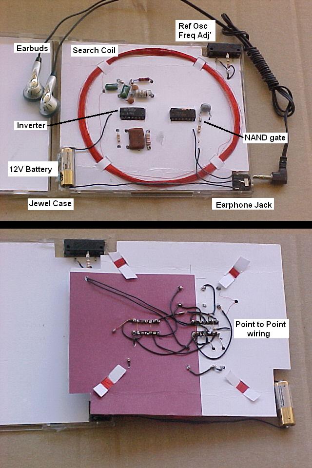
The form of physical construction is as follows:
As stated it all fits inside a CD jewel case.
The battery is a miniature 12v type used in; house cordless doorbell bellpush, key-fob car alarm controls etc (ie smallest physical size available)
In the absence of an on/off switch I have used a ring/tip/sleeve
audio socket in a way that the negative connection from the
battery is completed by the insertion of the earphones plug.
Cheap replacement "earbuds" (as used with popular I-PODs) are recommended: plug wiring must be altered as shown in the schematic; left and right "ears" bridged in parallel, then the ring and tip connections act as a switch closure when plugged in, and also connect to the "earthy" side of the circuit.
No volume control is provided; alteration of 1K earphone series resistor will change things.
Components are physically mounted on white cardboard.
Discrete component ends "pushed-thru" and Ics sit in a cut-out area.
All connections are soldered using insulated wire and "quigg’s" (pigtail spirals formed by winding small gauge wire around a small drill shaft or sewing needle etc) into which all connections are inserted and flowed with solder.
Front and rear cardboard sleeves disguise the contents of the CD case!
We have used this metal detector to determine which of a 1 in every 3 package of popular breakfast cereal contains a battery operated LED torch.
(to coerce children to purchase product) Saves buying a lot of boxes of cereal hoping that one MAY contain the desired free promotion, and satisfy the kiddies desire!
Other uses are; detecting nails is the wall, wiring runs, all the usual things.
Once again; I cannot claim originality of design; however the
construction and technical write-up is my own doing.
Enjoy!!
Ref 1 Silicon Chip Magazine (Australia) Mar 1991 pg49 (Cct & Design Ideas)
Ref 2 TTL cook book Don Lancaster 1974 Page 215
Ref 3 CMOS cook book Don Lancaster 1978 various.