
One of the biggest areas that radio enthusiasts place the most effort must be antennas. In recent years this has been my greatest goal, mainly because I have a really small garden. In the previous apartment I had no garden at all, so the 20m frame antenna came into being. Since moving into this house I have already experimented and published an article HF Antennas For Small Spaces, where I documented the results of many tests and the current antenna I am using.
During the summer I used the HF bands working portable from my car, using a 5m long MFJ-1979 antenna and a huge loading coil. Today I am single, so I have treeted myself to a new batchelor 2-seater cabriolet sports car. The boot (trunk) is really small (not even enough room to hide the road-kill, or the bicycles they were riding). Even the portable wooden box will not fit in the car anywhere. So I need an even more compact antenna.
I recently bought a bulk pack of telescopic antennas, which ranged from 450mm to 1.5m in length. These all had a 6mm diameter botom section. They WILL work for HF portable but I wanted something a bit longer, at least 2.5m in length. There are commercial antennas available for £80 or so. I bought a "Telescopic Portable Flagpole" for about £4.50p.
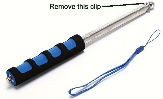
These portable flagpoles are designed for marchers and protesters, they are strong, sturdy and come with a flag of your choice. I wonder if they can be used as a baton? Unfortunately the Union Jack was out of stock. The Swedish flag was out of stock. The Spanish flag was out of stock, but they DID have a "Gay Pride" flag!! Not a problem, just throw the gay-pride flag away. The flagpole bottom section diameter is 14mm if you pull off the rubber handle.
This project shows you how I built the magnetic-mounted antenna that will drop onto the roof your car, can be deployed in 30 seconds, covers 7MHz to 30MHz without an ATU, will take 100 Watts easily, and can be used for any of the telescopic antenna elements listed above.
For the first contact I ever made with this antenna, I used only the 1.5m long telescopic element (6mm Dia.) and the antenna placed on the roof of the car. Situated on a hillock, open countryside, clear view of harizons, and running only 100 Watts. The first contact I made was to Iwate, which is in Japan, 7913km distance. I got a 4/2 report, but I thought it was fantastic for such a small antenna.
The basic concept of this design is to make a huge base-loading coil with taps, so that you can select a tap for any frequency you want. The coil effectively increases the electrical length of the antenna rod. An antenna that is too short will become capacitive, so adding an equal inductive reactance will make it behave resistive, at one frequency. This loading coil can be a challenge if you use thick wire, and turns that are touching can give rise to local heating and burn power. A 3D printed former gets around this.
Everything is built using a 3D printer, but you CAN build it in a more conventional way if you are prepared to use plastic drainpipes and other such components. Winding coils without a former and maintaining a constant pitch with uniform distances between turns can be a challenge, but you can use two wires together, wind the coil (secured with glue), then remove one of the coils, leaving you with perfect turns spacing.
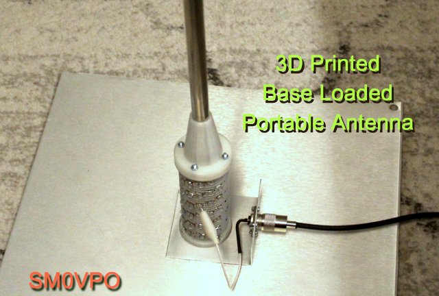
The car body itself is used as a groundplane, the 3D printed coil supports the telescopic antenna. The coil is mounted on a metal plate, about 500mm (1' 6") square, with a super neodynium magnet super-glued to each corner. This gives excelent strength and stability, even in moderate to high winds.
WARNING: You MUST put some form of protection under the magnets. Traditional mag-mount antennas are notorious for scratching cars to bits when iron filings, nails and bits of wire stick to the magnet. Always put an UNUSED sheet of polythene or something, under the magnets. Even newspapers work, if it is not raining.
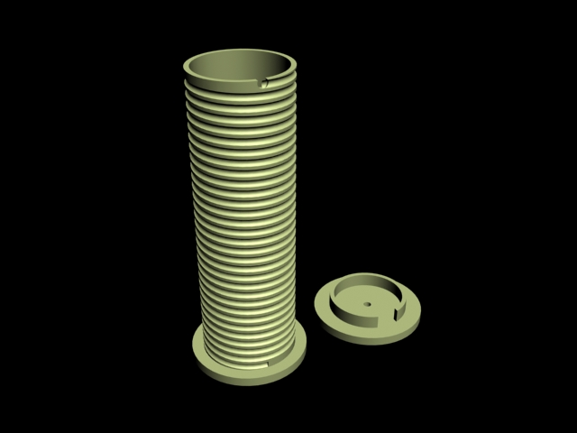
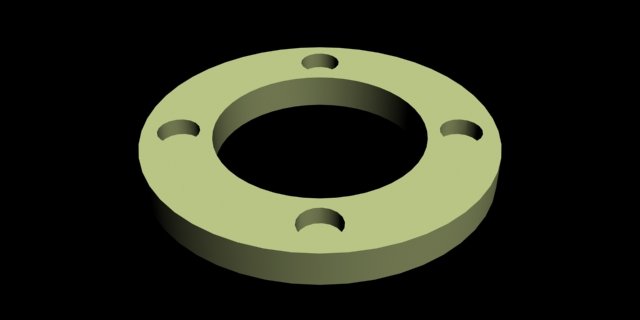
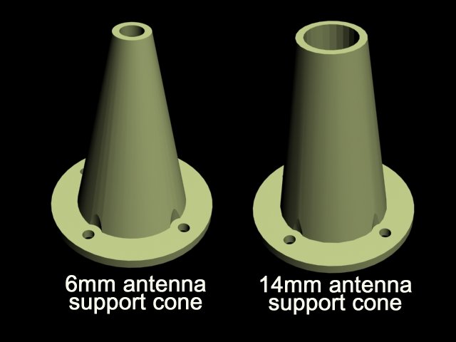
There are four 3D printed parts. The fourth part, the top cone, you can select to suit either a 6mm diameter telescopic antenna, or the 2.5 metre antenna with a 14mm diameter. The parts look like this:
Right-click and select "Save link as" to download the files:
Items 4) and 5) - select the one you want. If you have a telescopic antenna that is a little different then you can carefully drill the 6mm hole a little, up to 7mm. If your telescope antenna is smaller then you can put a little insulating tape around the rod to make it 6mm.
The prototype was printed on a Prusa Duplicator i3. Select support type "brim", Infill = 30%. I always run my printer platform at 60°C, but after the first layer has printed and succesfully stuck to the platform, I set it to 0°C. This prevents objects from warping. I run the nozzle at 197°C for cheap PLA filament, but now I am using E-PLA and that seems to work best at 205°C.
Download and print the files above, wind the coil, assemble them, and then make the soldered connections. The coil wire is household, multi-strand, insulated electrical cable, about 2.5mm Diameter.
1 - Fit an M4 machine screw through the hole in the bottom of the coil tube, using a washer under the screw head. The bigger is the washer then the more robust it will be. The screw head must be INSIDE the coil tube, as this is also used to mount the finished coil on the metal plate. Use superglue to make sure the screw head will not become loose and fall out, but do NOT get any superglue on the M4 nut or the screw threads. You will need to remove the nut later on, when the coil is mounted on the base plate.
2 - Wind 30 turns on the tube, laying the cable in the recess on the tube. Make sure it is really tight and there is no slack. You do not want any turns popping out of the recess and getting close to adjacent turns. I used a little dab of superglue in the recess every second turn, just to be 100% sure that it was solid.
3 - When you get to the top, cut off the wire so that there is sufficient to solder a 3mm solder tag and position it in the center of the coil tube. This you secure to the "tube cap" using a 3mm machine screw and nut. Again, use a touch of superglue to prevent the screw and tag from working loose.
4 - Fit the cap to the tube and use loads of superglue to keep it in position. I have added a lip to the cap to position it on top of the tube. The lip also gives additional contact with the tube so the supoerglue will stick like a limpet.
5 - Fit four M3 machine screws through the holes in the disc/plate. Use some superglue to keep the screws in position. When the glue has set, invert the plate so the screws point upwards and glue the plate to the top of the coil assembly.
6 - All you need do now is fit the coil assembly to the 500mm square plate using the M3 screw that is sticking out of the bottom. You just need to move the M3 nut from the bottom of the coil and fit it back again when the screw is pushed throught he 3mm hole in the base plate. Again, I used some super-glue under the coil, but that was probably me being a little paranoid.
If the screw protruding under the plate is long then there is a possibility it could scratch the car, so it would be wise to cut it off short. I put a fiber pad on mine, the sort they put under the legs of furniture.
7 - Now you can fit the telescopic antenna. They normally have an M3 threaded hole in the bottom, but if yours has something else then you need to fashion a U-bracket with 2 holes. This is an adapter so that the bottom side bolts to your coil terminal, and the upper hole is used to secure the telescopic antenna.
8 - Fit the antenna support cone over the antenna rod and secure it in place using 4x M3 nuts. The antenna asembly is now complete.
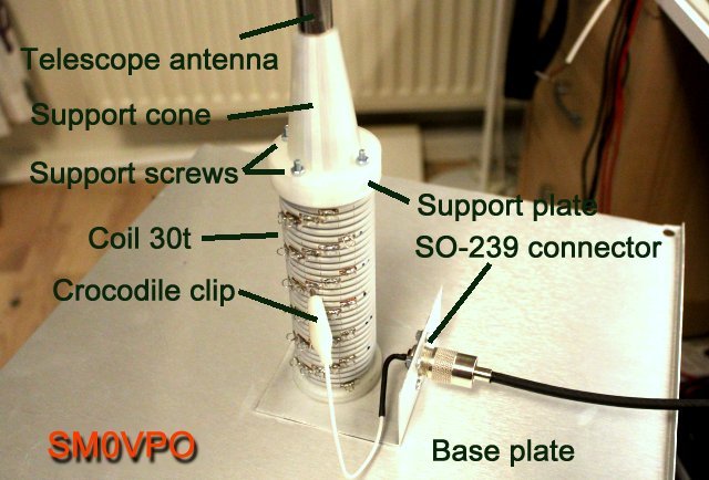
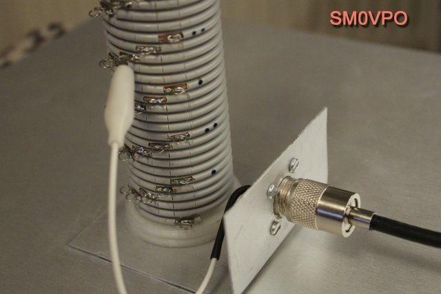
As you can see, the RF connections are braid/shield of the coax cable to the 500mm square plate, and the coaxial cable centre-conductor is coupled to the turns of wire using the crocodile clip. I also fitted an SO-239 connector so that I can easily dismantle, and reduce any wear and tear.
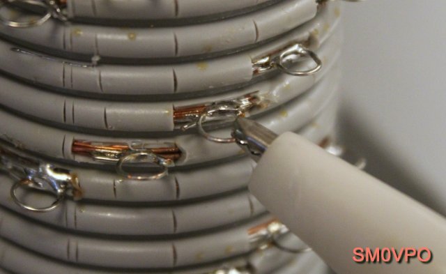
I spent quite a bit of time experimenting with this and the best method I found was to use some 0.8mm solid copper connecting wire, soldered to the turns of the coil. I used a scalpel blade to mark and cut the top layer of insulation to expose the multi-strand wire of the tuning coil.
Notice that the connections to the coil are all staggered by 5 turns so that there is plenty of space to make the connections, and you can select any tapping at 1-turn intervals. Instead of a lengthy description, here is a photograph that shows you exactly how I did it. I formed small loops that would easily take a crocodile (aligator) clip.
One small point here is that the feeder-cable should also lie flat on the car body. The 500mm square plate forms a capacitor with the car body, effectively grounding the plate. This is perfect for 7MHz upwards. For 3.5MHz (with the extra coil, see Adjustment below) I saw there was a little RF on the cable braid, so increasing the area of contact witht he car body makes it aceptable. I also tried laying a few 1m insulated crock-crock jumper leads, clipped to the 500mm plate, laid on the car roof. That made it perfect.
In accordance with the following table, extend the telescopic antenna section to the lengths shown. Connect your feeder to the top tapping (zero turns), then use the bands normally.
| Band | Frequency | Length |
|---|---|---|
| 4m | 70.2 MHz | 1.04 m |
| 6m | 50.1 MHz | 1.46 m |
| 10m | 29.7 MHz | 2.45 m |
| 10m | 29.0 MHz | 2.52 m |
| 10m | 28.0 MHz | 2.60 m |
| 12m | 24.9 MHz | 2.93 m |
| 15m | 21.7 MHz | 3.36 m |
| 17m | 18.1 MHz | 4.00 m |
| 20m | 14.2 MHz | 5.15 m |
This is all very well if you use an MFJ-1979 antenna that has a length of 5.4 meters. If you only have the 2.5m telescopic flagpole, or even shorter, then it will always be extended to maximum. In this event you need to use the coil taps.
Assuming you are working on lower frequencies and the telescopic antenna is shorter than 1/4-wavelength, then you need to use taps on the coil. For this you will need a VSWR meter. Do NOT use the radio's internal ATU, if it is equipped with one. We need to get the antenna correct so that it is matched before using any radio functions to make fine adjustments. I do NOT use any ATU at all. My VSWR is always better than 1.2:1 on any frequency I use. You can number the taps and make a noet of the tappings you used for any given band and frequency.
Turn OFF the radio squelch so that you hear background noise. Touch the crocidile clip to each turn in sequence and select the tapping with the highest noise.
Set your radio to CW or FM and turn the power level down as low as it will go, but enough to give you a forward reading on the VSWR meter. Be sure the frequency is clear before keying up the transmitter.
Key up the transmitter on the desired frequency and watch the VSWR meter reverse power. Now move the crocodile clip to the tap above, then the tap below and observe the VSWR. This will tell you if the tapping you need is above or below the current tapping.
When you have got the correct tapping the VSWR should be better than 1.2:1 but you should be able to get it so close that you cannot get any reverse power reading at all, so it looks like a 1:1 perfect VSWR. Now you can use the radio's internal ATU if you so desire. Remember that an ATU deliberately generates and internal tuning error that cancels out the external error. It is better not to have any error in the first place.
If you are using a 2.5m long telescopic flagpole, then the top tapping (zero turns) should be perfect for 28MHz. You will need typically 8 turns for 14MHz, 14 turns for 10MHz and 20 turns for 7MHz. These values can vary somewhat, depending on your construction differences. If you use a 1.2m telescopic antenna then it may not be so good at 7MHz. If you tune up at the center of the band then you can get close to 1:1 but towards the band edges the VSWR may rise to 1.2:1 which you can correct by adding or removing one or two turns.

One little trick I found is that I can re-use the coils I wound for my garden HF antenna and get the antenna to operate down to 3.5MHz, or tune to 7MHz using the shorter telescopic antennas. With really large coils and short antenna elements, the efficiency falls, but it can still get you on lower frequency bands.
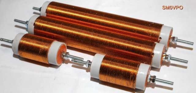
The larger coils may be a bit over-kill, but I will leave the experimentation to you. You can put a crocodile clip directly on one end of the coil and connect the feeder to the other end.
You can also add a "capacitance hat" at the top of the telescopic antenna to make it electrically longer. This can simply be a crocodile clip attached to a bit of self-supporting wire, mounted horisontally, maybe 20cm long. There is no reason why you cannot add a number of hats, maybe four, to form a star. These will also have the effect of increasing the efficiency a little.
One thing I hate is rain. I have operated in pouring rain, but only after I made a little modification. I took a 1.5L Coca Cola bottle, cut off the bottom, made a 14mm Dia. hole in the cap, then put this over the antenna so that it covered the coil. That worked very well, but if you have more than a little light drizzle then a bit of insulating tape, or silicone grease at the bottle top will do the trick. I used kids modelling clay because I just happened to have it available after copying some keys (don't ask).
In this article I have shown you a very small but very effective HF antenna for portable use. I you are working portable for a day, or participating in a contest, then you will want to have more "metal in the air". But if you just want to work the HF bands in your lunch break, then this is the perfect antenna for you.
Do not be decieved by the simplicity and small size of this antenna. As a vertical antenna it has quite low-angle radiation and it is omni-directional. If the telescopic element is shorter than 1/4-wavelength then you can expect a couple of dB of loss. But remember that one S-point is 6dB, so if this antenna has an efficiency 3dB worse than a full 1/4-wavelength, then this is only about 1/2 an S-point at the receiving station. If you operate on a hill in the countryside, as I do, then the environment is wonderfully silent W.R.T radio interference (but I have not tested a Tesla or any other electrically operated car!!).
I hope that this project has given you some "food for thought". You can always e-mail me at harry.lythall@[my domain].com. You can even use oeieio@hotmail.com or hotmail@sm0vpo.com as they are both valid e-mail accounts for me, although I would prefer that you visit my messageboard if you have any questions about this or any other project. I always look forward to receiving feedback, whether it be positive or negative 😊
Very best regards from Harry - SM0VPO
Return to INFO page