
You all know me, I am a real vintage lover. I remember the days when ladies used to show a stocking-clad leg, in the 50's, 60's and 70's. I remember the germanium transistor radio, when the quality was determined by the number of transistors. I used to have a Vesta Vixen, 2-band (with bandspread at the top of the MW band). It had 7 transistors (one used as a detector diode).
This is a nice vintage audio amplifier that is so easy to construct. I have included it in my homepages because unlike the modern, transformeless, solid-state amplifiers, it can be used for experimenting, due to the transformer output. This type of amplifier is still of great interest for the enthusiast, from a simple bench amplifier, light-beam telephone, or an intercom. This little amplifier is an excellent beginners project, and if you do canibalise an old radio for the parts then you will get some good soldering experience. Just be careful to use a solder-sucker or solder-wick to free the component legs of the transformers and IF transformers, so that you do not damage them on removal.
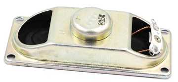
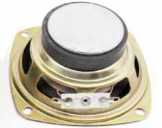
I remember in days gone by, around 1964, when I used to dismantle old MW transistor radios for parts. I would build many projects with this minefield of components. Today you can buy an old AM-only transistor radio for as little as US$1.50 to $2.50 from www.amazon.com, www.aliexpress.com or www.ebay.com. This will give you a cheap speaker, audio transformers, 250pf + 250pf tuning capacitor, as well as IF transformers and other "goodies". These transformers are a little hard to come by, but I recently bought some of them, new and unused, but I had to pay $2.50 a pair. The ones I got will give a little more power so I believe they are worth extra money. If you have difficulty getting the transformers, then you can google for 600Ω 1:1 audio transformer and then re-wind them. In the circuit I have given the turn-ratio of the transformers beneath the transformer symbols.
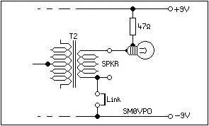
The wire link "Link" is normally fitted, in fact no link was used in the 1960's radio, but this is a good addition for the different possible uses of this amplifier. It is common practice to ground one side of the speaker, but if you use the amplifier for other things then you may need the transformer output to be isolated from ground. In this event simply remove the Link.
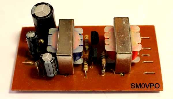
One small point, if you look very closely you will see that the transistors are reversed. This because I got the transistor connections mirored when I laid out the PCB. It is now corrected. The PCB and component overlay drawing is correct.

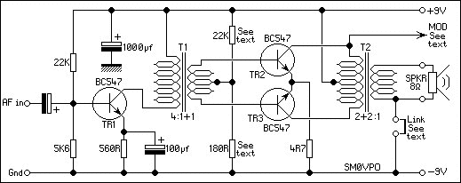
All the transistors in this project are modern(?) BC547, 2N2222, or just about any NPN small-signal silicon transistor rated at about 250mA upwards. Just be careful to observe the connections of the transistors. TR1 (the one on the left) has the input to the Base and the collector connected to T1 primary. TR2 and TR3 (the other two) have their Bases connected to T1 and their Collectors connected to T2. TR1 is a simple class-A amplifier (linear) and gives a nice audio gain. T1 is a phase-splitter that drives TR2 and TR3 in anti-phase. TR2 and TR3 are run in Class-AB, so each transistor amplifies only half of the signal. The two halves of the signal are combined in T2. That's it - simple! The complete project is mounted on a single Printed Circuit Board (PCB), with the exception of the volume control. The PCB size is 70mm X 40mm (2.75" X 1.6"). The foil pattern is shown below:
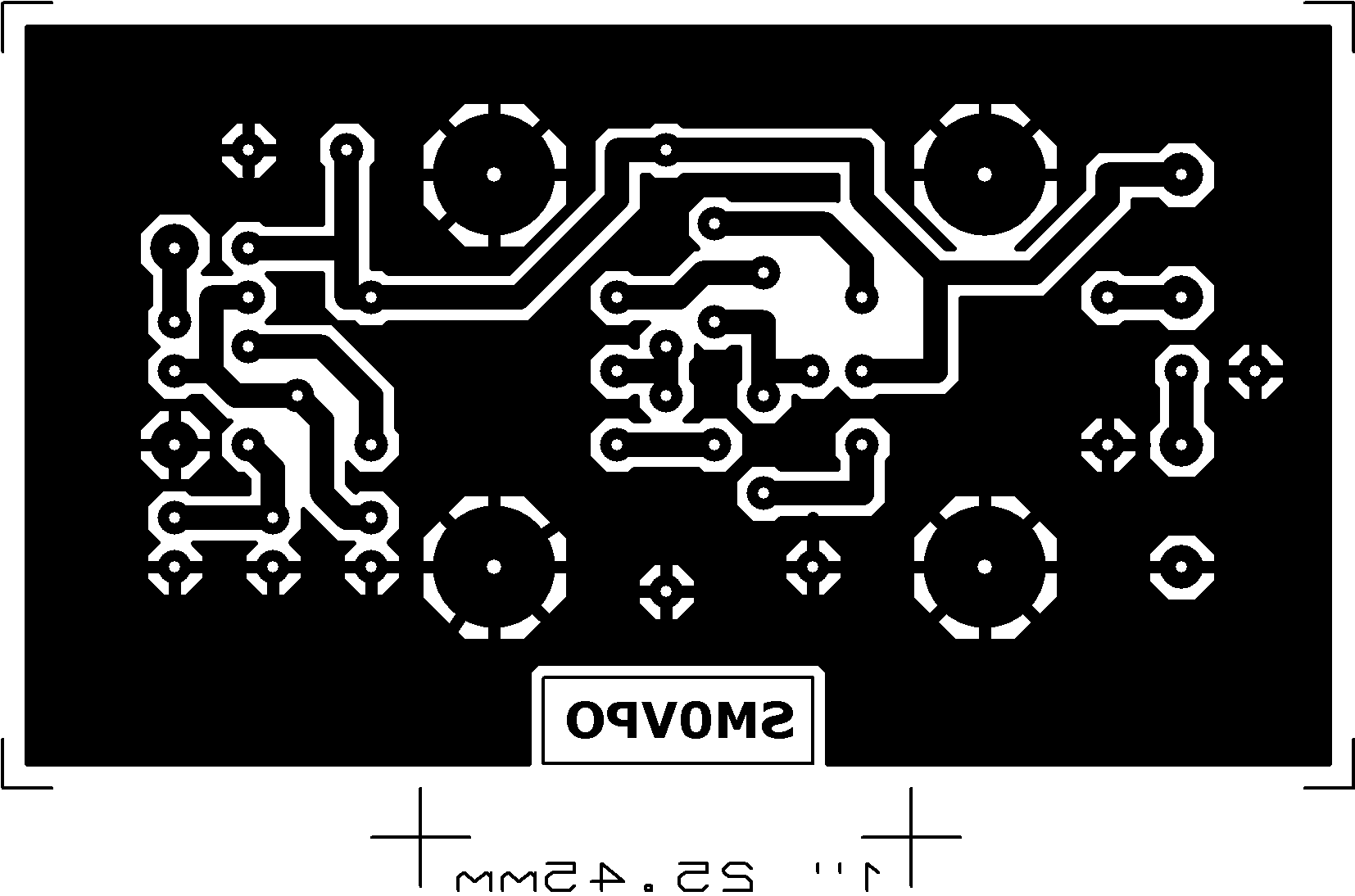
The picture is reduced in size a little for this document, but the scaling is done in the HTML file. You can right-click the picture and select "Save image as...", or you can click on this link 500mW_retro-af-amplifier_pcb.jpg (Opens full-size in a new window). The text "SM0VPO" should be the correct way round if you read it from the copper side of the PCB. If you are to print it to OHP film for photo-etching, then in your graphic program DO NOT RESIZE. Set the printer configuration scale to 12% and this will not affect the resolution. Alternatively you can change the pixel/inch from 72 to 600 pixels/inch.
The amplifier works fine with the components shown, but if you need the full output then replace the 180R resistor with a 1N4148 diode (cathode to ground) and reduce the 22K down to 10K. This will also make it more tolerant to supply voltage changes. The 4.7Ω resistor is fine, but on the prototype I used two 10Ω resistors in parallel. I calculated that the peak current could be as high as 100mA, which means that ¼-Watt resistors may possibly get a bit warm. This is only the peak level - they remained stone cold. With higher supply voltage the amplifier can deliver more than 500mW. If you use smaller transformers, then you may not get the full 500mW. Most of the really cheap radios have the smaller transformers. The ones I used are 20mm wide X 15mm high. You could take a couple of 2.5 Watt mains transformers and rewind them.
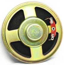
In the 60s the loudspeakers were cheap and nasty, but they were adequate for a personal transistor radio. Most low-power loudspeakers use high-power magnets that were not available in the 60's. The speakers today are much more efficient and have a much better frequency response, especially if they use nedynium super-magnets. 500mW may sound like a low power, but it is only ¼ of the audio volume your mother would have complained about from your old Dansette gramophone player pushing about 5-Watts from an EL84. With a modern speaker you will be really surprised how much volume you can get out of this little amplifier. In general, the smaller the magnet so the less efficient is the speaker.
Construction is dead easy. I suggest that you mount the horisontal resistors flat on the board first, then the other passive components, then the three transistors and the transformers last. I like to use 1mm fibreglass circuit board, which have a little bit of flexibility. So when I mount horisontal components, especially glass diodes, I usually put a bit of thin card under the components so that they are mounted about 0.5mm above the board. This can eliminate mechanical stress that could damage components if the board is flexed a little. You will also note that the PCB I used for the prototype is that ancient, cheap SRBP stuff. As I stated, I love vintage. I use it for prototypes, but since this project is a 1-off for me I decided not to re-build it it on the "good stuff".
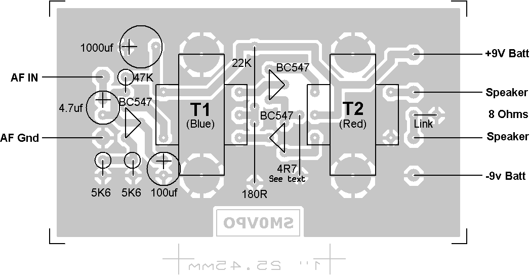
I have not added a volume control on the PCB, but any potentiometer of about 4.7KΩ through to 25KΩ can be used. If you fit it inside a box then the volume control and speaker will be mounted at the front of the box. The wire link "Link" on the PCB is normally fitted, but if you want to use the audio output for another purpose, such as the AM modulator or light-bean telephone, then do not fit the link. Then you can use the output for a number of other applications. If you do not fit the link then the amplifier will still drive an 8Ω loudspeaker.
Connect +9v to the power terminals, but if you are using a bench PSU then set the current limiting to 50mA. If there is a short on the board, or one of the power transistors are reversed, then this will prevent any expensive damage. If you only have a battery, then connect a 15Ω resistor in series with the +9V wire. If there is a short then you will get a large voltage drop across the resistor, instead of burning something. The trick with any power circuit is not to let the internal smoke component escape from the transistors. It the amplifier is working properly you should get about 0.75V across the 4K7Ω resistor.
The transformer output stage makes this little amplifier really useful for other things that are not so easy to implement using modern amplifier designs. For example:
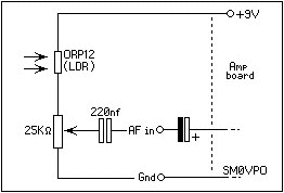
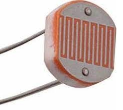
Fit the "Link", connect a 6V 40mA MES lamp in series with a 47Ω, and connect this between the speaker live to the +9 Volt supply and you have made a "Light-Beam Telephone". Just put the lamp in an old torch reflector and you can shine it on an OC71 (with the paint scratched off), or an ORP12 Light Dependent resistor (LDR). The LDR or OC71 can be used with a resistor to give audio into another similar amplifier, and you can fit the LDR to another torch reflector to get a good range. You should be able to get a range of up to about 20 metres, even more at night. The audio quality is a little bit muffled, but this is due to the time it takes the lamp to heat up in sympathy with the audio waveform. If the audio is a bit weak then connect the lamp and 47Ω resistor to the MOD output. This is exactly what I used in 1962 when I first built this amplifier. Today there are high-power LEDs that will give a better audio quality, and extend the range somewhat. Maybe you want to try infra-red diodes to make the beam invisible? If you have a defective LED 230 Volts lamp, then they contain several 1 Watt LED lamps in series. They usually strike at about 8 Volts. Use one of these instead of the 6 Volt lamp. This will also increate the audio quality and give you possibly 60 metres, or more, in daylight
You can extend the range to several hundred metres. Replace the MES lamp with the LASER module from a red LASER pointer, the type sold for $1 to point on the screen when you give classroom presentations. You will need to adjust the 47Ω resistor value. A good starting value would be about 150Ω, then reduce the value to get a brighter beam. This method gives a really good audio quality and you do not need to put the transmitter LASER in a torch reflector. Many of these lasers have a screw-adjustment at the front of the LASER module so that you can focus the beam. If correctly setup then you could get 500 metres or more. If you need to increase the modulation depth of the LASER then you can put an electrolytic capacitor across the dropper resistor.
The "MOD" connection from T2 will give you 9V DC with 12V to 15V of audio superimposed on it. This is perfect for modulating the output stage of a low-power AM transmitter of up to about 500mW. T2 therefore eliminates the need for a modulation transformer that would be needed if you were to use a more modern amplifier design. Using this technique you can listen to your old cassettes on that vintage MW radio that is sitting idle on the top shelf in your shack. Remember that it is illegal to radiate Medium Wave transmissions more than a few meters.
Stuff your MP3 player headphone signal into the amplifier input and you can have a portable MP3 player on loudspeaker. I have used this from my Samsung Galaxy mobile telephone and it works a treat. If you have a decent speaker then it will give a lovely, loud, portable sound.
Use an electret condenser microphone at the input of the amplifier. Place the microphone at the center of a parabolic reflector, and listen to the output of the amplifier with headphones. Point the parobolic reflector at people some distance away and you can hear conversations quite clearly. With an electret condenser microphone and a 300mm Diameter reflector you should be able to eavesdrop on conversations 50 metres or more. Many satellite receiver dishes have a deliberate poor geometry so that they can be more easily adjusted when trying to find a staellite.
If the geometry of the reflector is good, then pointing it may be a little difficult since the beam width is quite narrow. If you use a satellite dish then you could get a few hundred metres, but remember that many satellite dishes do not a perfect parabolic geometry. For mine I used a 200mm parabolic reflector made of plastic. 200mm is the limit of my 3D printer.
A quick word about the law. In most of Europe it is perfectly legal to use electronic equipment to record conversations without people knowing, BUT you must take part in the conversation you are recording. You may NOT publish the recordings. This information is given for academic knowledge. I do not know how the law applies if you are simply listening, but not recording. The law probably does not apply if you are recording birds twittering in a forest - birds to not have any legal right to privacy.
This is really interesting, and you can have a lot of fun with it. Use a single headphone, canibalised from an old Sony Walkman. These work well as a good microphone, and also have a good output level as a small speaker. They used to give away these types of headphones when you travelled British Airways Club-Class (otherwise you had to buy them). If you travel by Ryan-Air then forget it, you will get nothing. Today you may be able to cannibalise these ear-buds headphones used in your mobile telephone handsfree. They are smaller and give a narrower beam width, but the audio output can be lower.

Remove the foam cover and put the Sony earphone at the focus of a parabolic reflector. It will work as a microphone. Listen to the amplifier output using normal HiFi headphones. This is the same as the directional microphone above, but the earphone element is about 2.5cm Diameter, which means that the beam width is not as good as using the electret mic. Now you can add a switch to reverse the amplifier direction, using a Karaoke dynamic microphone into the amplifier and the Sony earphone at the reflector. Now you can talk back to the people to whom you are listening. Once again, a larger reflector will increase the range, 500mm diameter should be ok for 50m or more.
I did this in Saudi Arabia and pranked a couple of 8-year old children. I found that children can accept a person (Eustace) who "came back as a tree". The kids accepted the talking tree beside the wall, but their mother really freaked out when the tree talked back to her; totally hysterical!!
I hope that this project has given you some "food for thought" (or maybe some evil pranking ideas). You can always e-mail me at harry.lythall@[my domain].com. You can even use oeieio@hotmail.com or hotmail@sm0vpo.com as they are both valid e-mail accounts for me ;-) although I would prefer that you visit my messageboard if you have any questions about this or any other project. I always look forward to receiving feedback, positive or negative ☺
Very best regards from Harry Lythall
SM0VPO (QRA = JO89WO), Märsta, Sweden.