
Now this is a circuit that is interesting. It is a push-pull power amplifier miss-using voltage regulators as active devices. The circuit can be used for audio or radio frequencies. This unit will deliver over 250mW before the 78L05's begin to restrict the current to 100mA (peak). If you use 1-Ampere bypass transistors then you can get a nice comfortable 2.5-Watts out.
This is simply a pair of 78L05, +5V, low-power voltage regulator chips, each of which will amplify one half of the input waveform. Transformer T1 isolates the input to the amplifier and gives two anti-phase signals to drive each of the voltage regulator inputs (reference inputs).
The 5V regulators each deliver +5V, which is fed though the output transformer T2, with the centre-tap connected to a 5V Zener Diode. The Zener will not conduct (much) until the voltage rises above +5V DC. The two +5V out pins of the regulators are modulated with the input waveform, so either side of the transformer is driven in antiphase.
5.0V is not a prefered value, but I had a few in my junk box from one of these "mixed bulk packs" you get at radio rallies. 1N5222 is a 400mW 2.5v Zener diode, and you could use two of these in series. You could alternatively use A 5.1V Zener and use a germanium diode to raise the T1 centre-tap by 130mV.
The amplifier itself has a fantastic power-rail ripple rejection, due to the action of the 78L05 regulators. They are simply voltage followers with a +5V bias.
The active stages give absolutely no voltage gain whatsoever, but they give about 100x current gain. The transformer T1, on the other hand, can be used to realise voltage magnification. The input impedance to each regulator ref pin is about 5,000 Ohms, so using a 50 Ohm input you can have a step-up turns ratio of 1:10+10. This means you can easisly realise a power gain of 20dB or so (100x the power).
If you use the technique of bypassing the 78L05 with a power transistor, then you can get over 30dB of gain. This is how it is done:
The current drawn by the regulator also pushes current into the base of the PNP transistor. This causes it to conduct, and the collector current is added to the output current from the regulator. The regulator therefore draws less current, and the bypass transistor does all the work.
The 10nf (10,000pf) capacitor prevents the 47 Ohm resistors and other capacitances from forming a time-constant that could reduce the response time at higher frequencies.
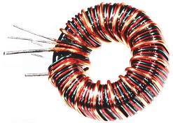
T1 is simply a 1:10+10 (turns ratio) transformer. This can be wound on a very small ferite toroidal ring. The secondary winding should be "biflar" wound (two bits of wire twisted together before winding). This will make a nice broadband transformer. 5 + 50 + 50 turns will work fine for around 100kHz to 5MHz, but 2 + 15 + 15 will be perfect for up to 30MHz.
Any ferrite should work fine, but you may need to adjust the number of turns, depending on the ferrite you use. I have used small ferrite beads designed for VHF in this application, and I even used some unmarked ferrites robbed from a computer power unit.
For audio work you will need something a little different. Two small speaker transformers from ye-olde transistor radio can have the speaker coils connected in parallel and the driver coils in series. Alternatively you can perhaps re-wind one of the dinky ferrite transformers used in your old Black-&-Decker drill charger after the batteries died.
Although I have grounded the input transformer T1, you could have the input winding isolated from ground, and perhaps use a transistor driver stage ("see text" in the circuit).
If you are building the 250mW version then T2 must be chosen for the correct impedance, depending on your application. The transformer input is 4V AC at 70mA = 50 Ohms. T2 turns ratio should therefore be 3:1 (1.5 + 1.5 : 1) to driver an 8-Ohms speaker, or 1:1 (1 + 1 : 2) to drive a 50 Ohm load. 50Hz or 60Hz mains transformers can be selected for audio circuits.
You need to wind your own coils on ferrite rings for RF work. At 100mA a ferrite ring in the region of 2.5cm Diameter is more than adequate. The primary should be "biflar wound" so that you can ensure the two halves are identical. See below for a better description.
If you are building the 2.5-Watt version then T2 must be modified for the correct impedance, depending on your application. If you use the regulator bypass transistors then the output of the amplifier is 4V AC at 700mA = 6 Ohms. To drive a 10-Ohm speaker you can use a 50Hz or 60Hz mains transformer that has a 1:1 ratio, such as 6-0-6 and 12-0 outputs, and ignore the 115V / 230V windings.
To drive a 50 Ohm load you need a turns ratio of 1 + 1 : 6 step-up transformer. A total of about 30 turns is ok for 1MHz to 30MHz, and about 100 turns total for 100kHz to 5MHz. If you have a load of those cheap ferrite rings from computer power units (about 2cm Dia.) then you can stack 3 or 4 of them to form a bigger tube, using super-glue.
You could alternatively stack 2 + 2 of them, using glue, to make what looks like a pair of mini spectacles: one turn is in one ring and out through the other. You can get 2-hole ferites ready made from Maplins, Mouser or Conrad, if you do not want to go to the trouble of making then with cheap rings and super-glue.

For RF up to 30MHz you should select the power transistors for an ft of 150MHz or more. CB output transistors should work fine, as long as they are PNP devices.
Here are the pin connections to the 78L05:
I have not tried using a higher-current TO-220 version of these devices in these applications, but you may like to experiment a little for yourself. I have 1000's of these devices in the TO-92 (100mA) version and for me it is no problem to add a power transistor when needed.
If you intend to use this project as an RF power amplifier then I strongly suggest you:
Use a 10nf capacitor in series with a 10k-Ohm resistor between 78L05#1-out and 78L05#2-ref, and another 10nf capacitor in series with a 10k-Ohm resistor between 78L05#2-out and 78L05#1-ref. If there is a tendency to self-oscillation at RF then reduce the value of the 10k resistors.
The idea presented is somewhat over-simplified, but you can get more than double the output power by changing the biasing. If you use a 12V AC transformer and rectifier PSU then you will also have -12V DC available by adding a single diode and a low-current regulator. This allows the possibility of giving the 78L05 chips a -5V reference, so the output of the amplifier will rise from 4V AC to 7V AC. This can be done with a simple Zener diode and a control pot, plus a couple of capacitors thrown in.
Note that this doubles the output power, but will also increase the output impedance by 50%. This means that you have to add 50% more turns to T2 primary. Double the power is only 3dB, or 1/2 and "S-point", so it is debatable whether there is anything to gain, other than better stability from the operational aspect.
The benefits of this method are:
You will also get an improved crossover distortion figure, but the prototype was so low that I could hear nothing, even at very low audio levels where crossover distortion is most noticed.
This circuit is presented as a circuit idea. My "rats-nest" version is nothing to brag about, and there may not be any PCB, unless I loose the 6146 PA in my Yaesu FT101ZD. In which case I will use a couple of 5-Ampere devices to bypass the regulators and make a 20-Watt PA stage. Before this I need to do some experiments to measure the "slew-rate" and upper frequency limit of these devices. This I have not yet done, so I cannot guarantee that these experiments work at all frequencies and amplitudes.
Before you begin to build aby of these ideas I suggest you collect the transformers and/or ferrites you will need. It will help you a lot to decide the size of the project and the layout.
Very best regards from Harry Lythall
SM0VPO, Märsta, Sweden (QRA = JO89WO)
EA/SM0VPO, Nerja, Spain (QRA = IM86BS)