Cheap'n-nasty transistor radio's can be bought for as little as US$2.00 or GBŁ1.5 (but they are still a hell of a price here in Sweden!!). If you look at the cost of a 50mm speaker and a battery clip then you will have recovered your money in component cost, but there is much more that you can save using these radio's as a source of electronic components.
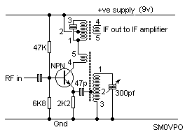
This radio receiver operates at 27MHz and uses no other coils than those robbed from one of those old cheap radio sets. You can buy a pack of coils from AES (see my component sources section on the main page). They have a limited stock of P-C216 which contains five coils for 95c.

The first step is to remove the IF CAN from the PCB. A solder-sucker with a rubber nozzel is ideal. Remove all the solder from the five pins and the two tabs from the can case. Do NOT be tempted to pull the can out from the PCB otherwise you will be left with a useless tin with the pins still stuck in the PCB. The trick is to press, equally, all pins from the track side of the PCB using the blade of a small screwdriver. If you need to loosen the pins then firmly grip them with a pair of pliers and waggle them around a bit to break and solder seal remaining. It is a bit tricky, but with a little practice it can work first time, every time.
Now that you have removed the can from the PCB you need to get inside the can and remove the wire and capacitor, then you can rewind it for any frequency you want.
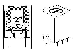
The inside of the can usually looks something like this:
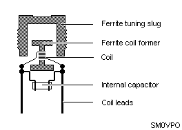
Here I have shown a cross section through the can to show all the 'gubbins' inside it. You can remove the tin case by pressing gently with a flat-blade screwdriver in the ferrite slug. All the insides should slip out without damage. Some coils have extra plastic cheeks between the former and the can. Note how the coil falls apart as you take it apart, then you can reassemble it the same way when you have finished re-winding it.
The inductor is wound on a ferrite bobin which is supported by a plastic base.
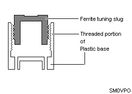
A hollow ferrite slug fits over the bobin and screws into the threads of the plastic base:
A capacitor is often fitted beneath the coil and this can be gently removed, if not required.
To calculate the number of turns you need is not really practical because of the variation between different cans. There are at least three common cans and all vary a little. As a general rule of thumb, you get about 4uH - 5uH per turn of wire, if the ferrite. slug is fitted. I always re-wind with 0.1mm enamelled wire as I rarely use the cans for RF power. The thing to do is to 'suck-it-and-see'.
You can often make use of existing cans if you have an idea what they are used for. A cheap'n nasty AM radio for the MW only band will have four cans that you can use. They are usually colour coded:
The only difference between the IF transformers is the Q-factor and the output impedance. Practically they can almost be interchanged with very little degredation in performance.
The IF use a tuned primary winding of typically 110 - 160 turns of wire with a 180pf - 200pF fitted across the coil. This winding us usually tapped at about 20 - 25% and connected to a centre pin. Unless you have any data on the coil then it is debateable from which end of the coil the tapping is made.
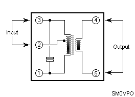
The oscillator coil (RED) usuaally has the same pin configuration but the intended use is shown below:
Have fun, de HARRY, Lunda, Sweden.
Return to INFO page