
There are several different standards for identifying component value and electrical unit magnitudes. Experienced constructors will no-doubt be familiar with most of these standards. The standard adopted in all my projects is a single letter for component values which replaces the decimal point values. For example, a 4700 ohm resistor is referred to in all drawings as 4K7. The letter used is:
Components use standard units such as the Ohm, Farad, Henry etc. but in the world of electronics we use components having values of minute fractions or many thousands of these units. A 1 farad capacitor could be the size of a bucket and is a few thousand-million times too big for radio work. Component values on drawings therefore uses:
R for resistance (Ohms)
H for inductance (Henries)
plus the following multipliers:
A 5M6 is therefore a 5.6 meg-ohm resistor
A 2K2 is therefore a 1.2 kilo-ohm resistor
A 6R8 is therefore a 6.8 ohm resistor
A 4u7 is therefore a 4.7 microfarad capacitor
A 3n3 is therefore a 3.3 nanofarad capacitor
A 2p2 is therefore a 2.2 picofarad capacitor
Resistors are normally 5% or 10% tolerance components. This is indicated by a GOLD or Silver band as the last colour of the colour code. The colour code for resistors is international and usually obeys the following colour code. There are Four colour bands on a normal resistor, these have the following numerical values:
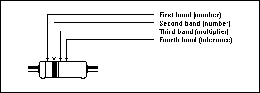
Numerical values for first and second band:
Numerical values for third band:
Numerical values for fourth band:
Note that the third band is normally a "multiplier" band which determines how many zero's are to be added to the value. Observe the direction that resistor colours are read. Some resistors, such as 1% tolerance components, require a fifth band. In this case the first THREE bands will have numerical values and the fourth band will be the multiplier.
A resistor with the colours YELLOW + VIOLET + RED has the value 4 + 7 + 00 = 4700 ohms = 4K7 and has a 20% tolerance. It is worthwhile noting that if the colours are read in reverse order they may still be read as one of the standard "preferred" component values. This is a common mistake sometimes made by the most experienced of constructors (including me). Example:
A 4K7 resistor, colour coded Yellow + Violet + Red, read in the wrong direction will become Red + Violet + Yellow, or 2 + 7 + 0000 = 270K which is quite different to 4K7. 220 ohms may be read as 1K2.
When fitting resistors to PCBs, I recommend that you fit all resistors so that all resistor values can be read in the same direction; from left to right, top to bottom. Electrically, resistors may be fitted any way around, but from a service/repair point of view, having the gold band to the right/down will add that "little extra touch" to your work.
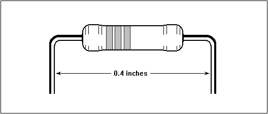
Horizontally mounted resistors should be preformed so that they are 0.4 inches between the bends, as shown above. This will ensure that the components are not subjected to undue stress after soldering. Tip: Use a short strip of thin cardboard beneath the resistor during mounting to ensure the resistor is not in contact with the PCB. This will prevent stress if the PCB is flexed. This is another "little extra touch" to your work.
Capacitors are most often marked without the use of the colour code. A capacitor bearing the marking 1n0 is therefore equal to:
0.000 000 001 x 1.0 farad - or:
0.001uf (micro farads) - or:
1nf (nano-farad) - or:
1000pf.
Small value capacitors are often coded with a three digit code; eg. 474. This is the value of the capacitor stated in picofarads. The third digit states the number of zero's to be written after the first two digits:
474 = 470000pf = 470nf = 0.47uf
Example:
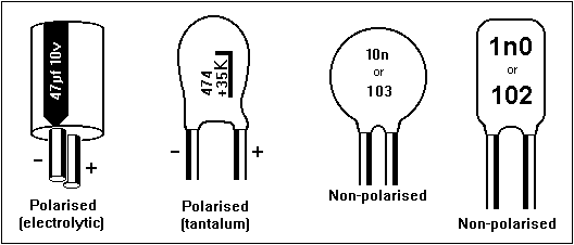
Capacitors having a value of about 0u47 (0.47 micro-farad) or greater are often Electrolytic or Tantalum (polarised) types. This means that it is very important which way round they are connected. Polarised capacitors are marked with the correct polarity on the body of the component. If two component leads are of different lengths then the longer of the two component leads is usually the + (positive) terminal. Non-polarised capacitors may be fitted to the PCB either way round, in the same way as resistors. It is good practice to physically orientate them so that they may be read from the front of the PCB. This will make it easier should service/repair of the PCB be necessary at a later date. Form the component leads so that the capacitor may be inserted in circuit easily and without strain.
In applications such as coupling/decoupling signals, and smoothing, Electrolytic and ceramic capacitors can be used. These are cheap and easy to obtain.
In applications where a capacitor is used for tuning or setting the frequency, such as oscillators and tuned amplifiers, then Polystyrene capacitors should be used. Suitable capacitors are often marked or advertised with the word 'NPO'.
Diodes are similar in appearance to resistors, but the body of the device is often made of glass. Most diodes have only one band around its body. This is used to identify the Cathode (symbol K) terminal. Diodes may only be fitted one way round. When fitting be sure that they are inserted in the PCB the correct way round.
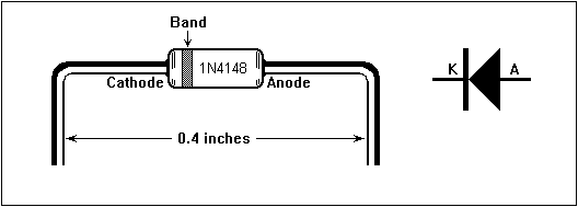
Diodes are best fitted horizontally to circuit boards. Form the leads so that they are 0.4 inches between the bends, as shown above. This will ensure that the components are not subjected to undue stress after soldering. Signal diodes are particularly fragile because they are often mounted in a thin glass envelope. When forming the leads, use a pair of pliers between the glass envelope and the bend. This will avoid stress at the point the wire enters the glass envelope.
Small signal silicon transistors are often mounted in plastic cases. These have three terminals, Collector, Base and Emitter and are often arranged as shown below. Note that there may be some differences between transistor types so check the transistor data before using them.
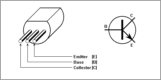
Transistors mounted in a plastic case will usually have the device number written on them. Expensive and special purpose or power transistors should be avoided until you are more familier with handling them.
Most IC’s used by amateurs are buffered CMOS types or special analogue devices. It is vitally important that all these devices are handled with care as they are often sensitive to minute electrostatic charges. Such charges may permanently damage these components.
I recommend that you observe the following handling precautions when using ICs:
CMOS ICs are supplied in an electrically conductive foam or tube. This ensures that all the component pins are at the same electrical potential. When inserting an IC into the PCB or socket, take hold of the PCB before inserting the IC. The IC and PCB will then be at the same voltage potential due to the resistance of your body.
Finally, the information I have presented above is only for your guidance. There are many frequent deviations from the general component forms I have described, so be carefull. I have been constructing since 1966 and I am still encountering components I have never seen or used before.
Have fun, de HARRY, Lunda, Sweden,