
Here is an easy-build high-performance VHF (or UHF?) local oscillator. There are no PCB foil drawings to play with and no coils to wind. There are two 90mm long copper wire inductors needed, but the good news is, you dont have to wind them. The first unit makes an excellent 10mW (+10dBm) exciter to drive a VHF power amplifier and you have an FM transmitter that spans typically 12 consecutive channels in the 144MHz band, or one WBFM (88-108MHz band) channel. It also makes a great Local Oscillator for a VHF receiver. It can be built for almost any frequency range, from about 30MHz to probably much more than 200MHz, and it is crystal stable.
When building VHF equipment, one must almost always begin the design somewhere within the HF spectrum, then convert or multiply frequencies. This means loads of coils and a long struggle to prevent other harmonics from breaking into the final system. The harmonics are always there, the question how low down are they? In this project I will build a generator for 130MHz. I need 10mW from it to drive a 144MHz to 14MHz multimode transverter. It is therefore very important that there is no spurious or other "crap" within 30MHz either side of my 130MHz signal (I don't really want anything elsewhere either). I really need 100mW so my VHF transmitter can go into the mixer at a high level, but the other 10dB of gain is contained in the mixer module and that is another project.
I am going to begin with a 26MHz TTL crystal square-wave oscillator. This could be either a TTL chip or a crystal module. I prefer the crystal module since these have a small frequency adjustment by voltage, and they do not require any assembly, just a little superglue so they have their legs in the air to form suitable anchoring points for other components.
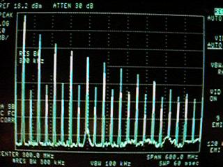
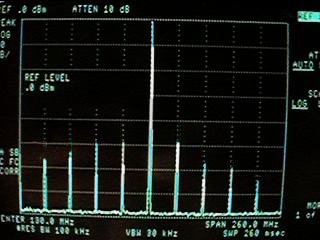
Here you can see the two alternatives, either a TTL circuit or a ready-made module. For the higher crystal frequencies you will need to be certain that the crystal is not a harmonic crystal, as this oscillator will only function at the fundamental frequency of the crystal, but it is just a suggestion. The 26MHz module is available from a variety of sources, such as QuartzLab, see my suppliers and links section. The oscillator modules also have a FM input that will shift the carrier a few KHz, which, at the 5th harmonic, gives us some 300KHz of deviation (looks like an ideal start for a WBFM transmitter!!). The left picture below shows the high harmonic content of these oscillators when viewed on a spectrum analyser.
Now we will blast this RF into a small-signal transistor to get a few milliwatts of power out of it. At this stage we are not too bothered about harmonics, in fact we want them. The more power we have, then the more we can have out at the frequency we are interested in. This is then followed by a very narrow band-pass filter. The output should be about 1mW at the 5th harmonic although it is about the same region for all harmonics, up to about the 10th. Here is what the final output looks like. It is then followed by a single transistor amplifer having about 10dB to 12dB of gain, raising the final level to +10dBm. This is sufficient to drive most VHF amplifers to get a few watts out, or to mix with TX and RX signal to convert to other frequencies.
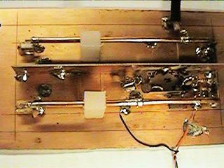
The secret of all this filtering is the use of copper rods and the preset capacitors that tune them. This makes the coil easy to wind, you just need zero turns for any band you like! Two copper rods are bent over at the ends so they can be soldered directly to unetched copper-clad board, see the right-hand photograph above. They could be soldered to pads if you want to raise the voltage, for example, adding a DC bias for transistors, etc. The two rods, in the above example, are 90mm long, mounted horisontally 12mm from the board. For 130MHz they are tuned with about 20pf (15pf + 2-10pf trimmer), but a smaller capacitor will bring them into the 144MHz (2-metre) band.
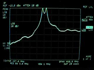
The chosen method of construction was the so called "ugly-bug" ("rats-nest" in English), mainly because a PCB does not really suit this project - there are so many mechanical considerations. As you can see in the photograph I have placed a shield between the two inductors. I will shortly place an aluminium shield over the whole assembly, but this will affect the coupling between the two resonators. Ah!!! Coupling, that is a good word. The two resonators are separated by about 60mm. This and the shield between them reduces the coupling so that we can have a decent response and filter out adjacent frequencies. At first sight it would perhaps seem logical to place them closer together to get a better coupling - not so! If there is too much coupling then the passband widens quite considerably. To the left is a view of the spectrum analyser when the two resonators are just 15mm apart, to the right is the actual response I want (almost):
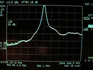
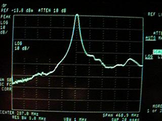
Coupling will be even further reduced when the tin-lid (aluminium) screen is fitted to give a response more like the one shown below-left, where the last remaining double-peak has almost dissapeared. Do not worry about the high base level only 30-40dB down on the peak in these photographs, this is due to stray coupling between my tracking generator and the analyser input. I am too mean to cut short my coaxial test leads for just three photographs. Sorry. When passing the original 26MHz (plus harmonics) through the filter, we finish with a signal like the one below right. As you can see, the unwanted signals are about 50dB down on the 130MHz desired signal.
Not bad for the 5th harmonic? It also works equally well on the ODD harmonics above about the 10th, or so. This project I am using for a transmitting converter. It only gives about +10dBm of output signal, but the amplifier/mixer stage also uses a single resonant filter that further cleans the output by about 25dB to the final spurious output level is better than 75dB down (-55dBm) on the 100mW carrier level (+20dBm). But, if you just want an FM exciter for 144MHz (or 88-108MHz) or the local oscillator for a VHF receiver, then this circuit is the one you want.
Ok then, that's it. Nothing more to say about it, so here is the circus diagramus confusicus and a picture of the completed project with it's 25mm high tin-lid fitted. The hole in the lid allows access to the frequency trim pot.
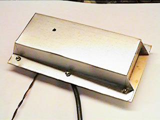
So what have I forgotten? Oh! Yes. The numbers at the tappings of L1 and L2 in the circuit diagram are the number of millimeters to the tapping, measured from the earthy end of the inductor. The earthy end of the inductors are not soldered directly to the copper groundplane, they are soldered to 10mm x 10mm pieces of copper-clad board and it is these that are super-glued to the main PCB. In this way they can be decoupled to earth by soldering capacitors, and even fed with a biasing voltage, as per the circuit. I also used a single 5mm x 40mm copper-clad board across the main board as a +10v line. That is about it! The next project will be the RX mixer plus local oscillator amplifer (+20dBm) and high-level mixer.
Very best regards, and have fun, from Harry - SM0VPO