
I used to receive so much e-mail that I often had no time on the workbench. Some mail is funny, but this you will find in my FASQ pages. I separated them because there were so many. I no-longer update this page since the https://sm0vpo.forumotion.com messageboard was created.
Q
I have tried to write to you several time because i have a problem with a schematic
of a oscilator. This is the third time i sent it.
(no name given)
A
Hi,
First of all, let me point out that this is a hobby, and not a business. When you
write to me I will try to answer your questions as soon as I can. But there are times
when it is not possible to reply to you immediately. I used to check my
 account every day, but unfortunately it is
starting to get so full of SPAM and viruses.
account every day, but unfortunately it is
starting to get so full of SPAM and viruses.
I live in the country, and family life requires certain comitments, as I am sure you are well aware. These comitments I place far higher in priority than my hobby. If I have little time, then the hobby can wait.
My job sometimes requires me to travel abroad. When that happens I cannot read mail. When I go on holiday I only do those things that can be done with a wife, on a beach, in a bar, on a plane, or in a pub. E-mail is not one of those things. When I am abroad I sometimes visit the messageboard if I suffer from Internet withdrawal symptoms, and there is an Internet Cafe around.
I am receiving over 120 SPAM messages a week. If you want to write to me, then please use harryvpo @ sm0vpo.com first, because that account is receiving the minimum amount of shit. Please also do not forward the address, or put me on a mailing list. If you have a technical problem then PLEASE use my messageboard. And if you can help others on the forum by answering their problems, then that would be appreciated.
Very best regards from Harry - SM0VPO
Q
Harry,
Why do you not sell kits to Swedes? You live in Sweden. Postage is
cheaper and more reliable. Do you not want to sell any kits at all?
Mvh Kurt
(I no-longer sell kits.)
A
Hi Kurt,
If I sell a USD7 kit (V4) to the USA then it costs me a little over USD3 in postage, and the customer sends me USD7 in nice banknotes: He sends me money, I send him a kit. This is just great: it covers my costs, envelopes and components, and a USD1 "thanks".
Swedes, on the other hand, refuse to put a banknote in the post. Swedes will quite willingly pay, pay, pay, and pay again, to all these "middle-men", such as "Svenskakassaservice" (the post office that does not sell stamps). It costs money; (USD6 for every transaction, plus another USD11 if it involves non-Swedish currency). It is no-longer possible to pay an electricity bill by cheque or cash. You have to pay it via the "Svenskakassaservice" (the post office that does not sell stamps). Ok, let me look at a couple of alternatives that Swedes demand:
POSTFöRSKOTT This is where you expect me to open (for a USD14 annual fee) a Giro account with "Svenskakassaservice" (tpotdnss). I then pay them USD7 to send the kit to you, and you buy it from "Svenskakassaservice" (tpotdnss), who in turn put the money in my account. Now I don't like this, because I only get about 2 Swedish enquiries a year, and I object to paying out money USD28 a year for the privilige of selling two kits.
AVISERING This is where you promise to pay me USD7, so you go to "Svenskakassaservice" (tpotdnss) and pay them USD12. They send me a chit for USD7, but I have to pay them USD6 to get it. Smart! (eller hur?)
I am not prepared to give away kits for free, and pay "Svenskakassaservice" (tpotdnss) for the privilige of doing it. I am not running a business, I "make" almost nothing. I pursue my hobby because I enjoy it, and I also get a kick out of seeing others get stuff working for the first time. If I sell one kit a month then I am happy.
As regards the cash I receive, I parcel it all up, once a year, and send it to my bank in England, where the charges are only USD2 to change the small amounts I handle, into English pounds. It is also why the V5 kit costs only Ł5, including postage: no exchange fees. It also explains why I can accept only USD and GBP.
Q
Harry,
I thank you for reserving the kit, but your method of payment *cash*
is not acceptable. Why cash? I will be sending you a personal check.
Regards Harry
A
Hello again Harry,
The Hamcom interface kit is only $10 to the USA, but if you wish to pay by
check (cheque) then it will be $21. If you send me a check for $10 I cannot
use it since it will cost me more that to get the money. I don't really make
a profit, but I will certainly not give away kits for nothing. Sweden is a
country where one does not ask the cost, except as a matter of interest. I
have been told that it is my duty as a customer to pay up and shut up. But
perhaps I had better give you a little information about Sweden.
Foreign checks cost $8 providing they are drawn from a "Swedish
crown account", otherwise an additional $3
exchange fee is charged. Most Swedish banks now refuse to accept or exchange
foreign currency. If, like me, you are NOT a banker, then we are both in the
wrong trade! The Swedish post office do not accept the "IRC", and would you
believe that many major post offices DO NOT SELL POSTAGE STAMPS!! I save the
US dollars and send them once a year (by registered post) to my bank in
England where they charge me only Ł1.5 to exchange any amount.
Best
Regards from another Harry
Q
Harry,
I still didn't get a good answer. I want to know what range I can get
with a given RF power ie. how many kilometers per watt? Your V5 bug gived +10dBm,
but what the hell is that for a power? Can you be a bit more specific?
Regards Confused
A
Hello again Confused,
Sorry, but perhaps I did not make myself understood. Anyone who can answer the
question of "how far can I transmit with ... ?" can also answer the question
"how long is a piece of string?". The transmitter output power only affects
the radiated signal strength. The range is governed by many other things,
including:
RX SENSITIVITY - A receiver with a poor sensitivity needs a stronger
input signal to receiver the transmitter. Use a radio with a poor sensitivity
and you have no hope of getting a good range. For VHF FM broadcast then a
receiver sensitivity of 20uV for 20dB quieting is Ok. 100uV for 20dB
quieting is piss-poor but 5uV is not too bad at all.
TX ANTENNA GAIN - If you put the RX antenna inside a biscuit tin then
you will not receive anything. Use a bit of "wet string" as an antenna and the
results are better, possibly 1/100 of normal. Use a centre-fed 1/2-wave
antenna and you are doing well. Use a 10dB gain Yagi and you can get 3x
the normal range. Use a 50dB gain parabolic dish (eg. the Greenwich
observatory antenna) and you can get possibly 300x normal range.
RX ANTENNA GAIN - see TX ANTENNA GAIN above and use exactly the same
parameters.
THE PATH LOSS BETWEEN THE TWO ANTENNAS - This means that a transmitter
operated in a coal cellar, cannot be received in another coal-cellar 10Km away.
There is too much stuff to attenuate signals between them. Signals are
attenuated by trees, soil, people, concrete, house-bricks, wet socks,
atmospheric layers, metals, animals, busses, vegetation, cross-polarisation,
or anything that obstructs the 0.6% first Fresnel zone (the thickness of
line-of-sight). Don't forget that the "bulge" of the Earth is also significant
in path loss calculations. If you want the path loss formula then Pl(dB) =
32.4 + 20 log(f) + 20 log(Km).
TRANSMITTER POWER - As the TX power reduces then so does the
available signal strength for the receiver to detect.
To answer your question, add the path-loss + TX ant gain + RX ant gain + TX power - Fresnel zone occlusion losses. If the figure you get is greater than the signal sensitivity of the receiver then you will receive the transmitter. ie. if the receiver sensitivity was -100dBm and your final signal available was -120dBm then you are not going to receive the signal. Now, lets us give some practical examples:
In conclusion, the distance you can get therefore depends upon your ability to reduce all the losses involved in the radio signal path, increase antenna gains and increase receiver sensitivity. Your V5 FM wireless microphone transmitter may give you as much as 500Km or only 5metres, depending upon where and how you use it. Try hanging it vertically on a bamboo pole by the antenna wire and place it on the roof of your home. Use a sensitive receiver with a 1/4-wave vertical antenna and you may achieve 3000-metres, depending upon terain. Now hide it inside the metal spring assembly of someones bed at ground level and receive it using a cheap insensitive receiver with a 20cm telescopic antenna in another room. You may be lucky to get 10-meters.
Power Decibels (dB) are 10x logarithm of the ratio between two powers. You cannot simply say a signal is XdB, that is meaningless (the Eiffel tower is 3 high). It must be related to another signal level (the Eiffel tower is 3x higher than the Blackpool tower). The common reference power levels are 1mW (0dBm) or 1-Watt (+30dBm or 0dBw). You can have anything as a reference, eg 1-volt (dBv), 1uV (dBuv), flatulence (dBf) for sound, or butterfly sneezes (dBbs) for mechanical power, any reference you want, as long as the reference source is known to the one who has to interpret your figures. You can, however, have a 10dB increase since this statement is comparative. As regards "what is +10dBm"; Ten milliwatts is +10dBm or -20dBw (dBwatt).
This all pretty basic stuff that you can get from your local library. I can not deliver more via E-mail and I am very surprised that I have devoted so much time to your question. I think I may use in in my questions page since this is a frequently asked question and perhaps others may learn from the answer.
Many thanks for visiting Harry's Homebrew Homepages.
Very best regards from Harry - SM0VPO
Q
Hello Harry,
Nice homepage. I need to know the difference between a condenser
and a capaciter and how you use them in radio circuits. Whats the diference? its
ok for people like you that know these things but it is confusing.
Thanks a
lot - Ted
A
Hello Ted,
A condenser is the old-fashioned name for a capacitor. The basic use is to hold
a charge to condense the pulsed waveform from a rectifier to a steady DC signal
or voltage, or forming tuned circuits. Condensers are still used by people (like
me) who experiment with wireless. Those who experiment with radio tend to use
capacitors. If you want to learn more then I suggest you go to your local library
where I am sure you will find the answers to your questions. Many thanks for
visiting Harry's Homebrew Homepages.
Best regards Harry - SM0VPO
Q
Dear Harry
I like your homepage very much and i have built two of the projects your kits,
namely high-power BUG & the TDA7000 receiver. I have ben looking at your
building blocks (misspelled) and think it would be good to include audio power
amplifer to your collection of kits. I would like an easily constructed amplifier
using comonly available components.
Please keep on the nice homepage - Winston.
A
Hello Winston,
And many thanks for taking the time and trouble to pass on a positive suggestion,
I think that is an excellent idea. If you now look at my homepage you will see that
I have indeed included an AF-amplifier kit capable of driving over four watts into
a 3-ohm loudspeaker and it uses commonly available components. By the way - the
miss-spelling is deliberate, in the interests of adding a little comedy. You are
only the second or third person to notice it in a year. Many thanks for visiting
Harry's homebrew homepages. Hope you have fun.
Very best regards from Harry
Q
Hello Harry
Where did you learn all this stuff? Can you show me how to be a good
home constructor? I am good at receiving lessons.
Best wishes - Rannug
A
Hello Rannug,
Firstly, I am not good, I have just writen a homepage about the little I
do know. The more I learn then the more I realise how little I really do
know. My advise to you is to simply build what you want to build. When
it does not work then find out why, experiment a little, blow up a few
transistors, wind a few coils. Build a couple of kits to start with (eg
CirKit from my links page). Unfortunately I am almost 50-years old so I
have blown up a fair share of components and that is all experience I
cannot send you by E-mail. The most important thing is to have fun.
Very best regards from Harry - SM0VPO
The first step to learning
is the knowledge that you need to learn.
Q
Hi Harry
I would like to add a radio frequency crystal to the FM Wireless
Microphone project to improve the frequency stability. Could you
please advise me as to how I could do it?
Regards from Fred Smith
A
Hi Fred,
There are two ways, replace the 2p7 capacitor with a 5th-harmonic crystal
and it will oscillate at the crystal frequency, if the 12p and the coil
are tuned to the crystal frequency. The second method is to remove all
components from the base circuit and add only 2x47K resistors, as in the
FM Mic V4 circuit. Add the crystal from Base of the oscillator transistor
to ground. If the 12p and the coil are tuned to the crystal frequency it
will oscillate.
WARNING
You will not be happy with the results. FM means Frequency
Modulation, this means that the carrier frequency is modulated +/-75KHz
(a total of 150KHz). If it is crystal controlled then this will not be
possible, in fact it will be impossible to modulate.
If you want
crystal stability FM transmitter then you should make a 10MHz VFO with
FM capabilities and mix this with a 90MHz crystal oscillator. After the
ballanced mixer you will need to filter the wanted signal to remove
all unwanted mixing products, then amplify the wanted signal to a working
level. This is how many commercial circuits operate, but they cost hundreds
of dollars. Now you know why. This project is supposed to be the simplest
TX for newcommers.
Very best regards from Harry - SM0VPO
Q
Dear Harry,
I am having trouble making boards that work I have not
succeeded to build your FM microphone because the board kopper is
coming of all the time. Other kits I have built are the same but some
are worse than others som just form bubbles in the kopper like in
wet wallpaper. Can you tell my why? Is there something I must knoe?
From Karl, SMXXXX
A
Hello Karl,
It sounds to me as if you are using a soldering iron
that is not designed for electronic work. You should use a soldering iron
of about 15 to 25-watts, such as an Antex or Weller. The temperature
should only be about 300°C to 320°C or so. Give me a call on 08 XXXXXXX
after 6-0-clock and we can discuss it. If you want we can take it in
Swedish.
Very best regards Harry - SM0VPO
Q
Hi Harry,
Can you tell me what kind of ASTU works the best for HF QRP
work? I need to get my VSWR down since it is about 2.5:1 and I have seen
so many different designs I am becoming confused. By the way, I like your
homepages very much and I will continue to visit them.
Regards from Patrick
A
Hi Patrick,
The best way to couple a signal to an antenna is direct
and without the use of an ASTU (ATU) since an ATU works on the principle
of two wrongs making a right. Any passive decice has a loss. A VSWR of
2.5:1 also means that less than 20% of your signal is wasted. This is
just a bit more than 1dB or a very small fraction of one S-point at the
receiving end. Unless you are chasing real DX then it may not even matter.
To correct it then adjust your antenna length a little. Many thanks
for visiting Harry's Homebrew Homepages.
Very best regards from Harry
- SM0VPO
Q
Hi Harry,
Wow!! What a great homepage you have. I have added a bookmark
to your pages and will visit them regularly. I really need the circuit
diagram of a VHF FM Transmitter for Wide-Band FM in the frequency range
of 88MHz to 108MHz. It should be crystal controlled and have a minimum
output power of 50 watts into 75 ohms. Please E-mail it to me.
A
All the circuits I have in electronic format are on my homepages. Those
that are not in electronic format I am unable to send to you. Many thanks
for visiting Harry's Homebrew Homepages.
Best regards Harry - SM0VPO
Q
Hi Harry,
I have just been visiting your homepages for the first time
and I must say that they are very impressive. I particularly liked the
article regarding the synthesised receiver but unfortunately the two
linear chips you quoted are difficult to get here. Have you ever though
of using common 4000 series CMOS chips? The 4046 and 4059 make a good
team for this application.
Best regards Bob
A
Hi Bob,
What an excellent idea! As a matter of fact I have designed a
CMOS synthesizer many years ago whilst I was working in England using
the CD4060, CD4046 and CD4059. If I can dig out the original PCB foil
pattern I used then I will indeed document it and place it on the home
pages. Very best regards DR Bob and many thanks for the suggestion.
73s de Harry.
Q
What is the best RX?
Answer please.
A
Racal RA17 or RA117. Ok?
Q
Helly Mr Lythall,
I am a fifth year student studying radio and electronics.
My end of term project is to design and build a short distance radio transmtter
that can be used in a suitcase so that if the suitcase should become further
than about 15 metres away from me (if stolen for exampel) then the receiver
alarms. Unfortunately I am not very good at designing so I wonder if you could
design such a project for me? Please E-mail to me the circuit diagram and the
PCB foil and I will be very gratefull.
Regards Gxxxxxx
A
Dear Gxxxxxx,
All the circuits I have in electronic format are on my homepages.
Those that are not in electronic format I am unable to send to you. Many thanks
for visiting Harry's Homebrew Homepages.
Best regards Harry - SM0VPO
Q
HI Harry,
I have been visiting your homepages for some time now and I have been
very impressed with all the new ideas you have given me. Your BUG is very interesting
and I want a circuit to make it more sensitive so that I can pick up sounds from
ten feet and give out more power. A 5Km range would be about ideal.
Best wishes from
Fxxd
PS How do I connect it to a telephone line?
A
Dear Fxxd,
Many thanks for visiting Harry's Homebrew Homepages. Unfortunately
the "BUG" as you call it is an FM Wireless Microphone that is intended to be a
toy or a constructional article to fire the interest of newcomers to homebrew. It
is most definately NOT in any way intended to be used for eavesdropping. The microphone
sensitivity is deliberately low so that you have to talk to it as you would with a
normal microphone.
You should NOT attempt to increase the range since most countries have very strict
laws about these devices and eavesdropping. You may notice that many toy stores
sell such devices but they are not considered as transmitters due to the small
radiated power. If you increase the radiated power then you could find yourself
in "deep shit" and your transmitter could even become more noticeable to your
neighbours and other band users. I am sorry Fxxd but I cannot (and will not) help
you with the information you seek.
73s de Harry.
Q
Hello again Harry,
I have built your FM Wireless Microphone and it worked
perfectly after I located the frequency. As described it originally operated
around 115 mHz and I had to increase the tuning capacitance a little to find
it on my FM radio set. I have now built the PCB version and this operated at
106.7 mHz imediately, exactly as described. Could you please advise me if
anything can be done about the following:
1. Both versions seem to be a little unstable in frequency.
2. The basic version (not the PCB) is also very sensitive to vibrations.
Very best 73s and thank you for the information you are putting on the net.
A
Hi OM (I didn't get your name),
I am very please that you liked my homepages and that you have had some success
with my projects. As you may appreciate, a VHF L/C oscillator is unstable by
definition. There is no way you can connect an antenna to a tuned circuit and
not get some change in frequency. If you reduce the coupling to the antenna
you will improve the stability but reduce the radiated output power. I will
update the homepage project with pictures of the mods to the PCB version, but
it should not be necessary if you are using a receiver with AFC.
attach - bug-pik.jpg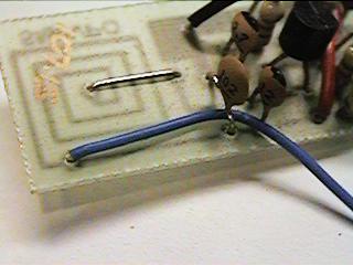
The basic version of the Wireless
microphone uses a coil which is a spring. This will vibrate if not supported
and copper wire will also expand with temperature. This makes the Basic version
both unstable and microphonic. This is also why I recommend the PCB version. If you
were to get your wife to wind the coil for the basic version then it would
very probably operate at 84MHz or anywhere between 84MHz and 115MHz. Again I
recommend the PCB version.
Many thanks for your feedback, I will make
an addition to the FM Wireless Microphone in view of your comments.
Very best regards from Harry - SM0VPO
Have fun, de HARRY, Lunda, Sweden.
Return to INFO page