
This project is a two-transistor amplifier stage that delivers a little under 20dB of gain. It requires no tuning or alignment. Wideband techniques have been used in the design, and the circuit is equipped with a "low-pass" filter. The project has been designed for assembly on a single-sided printed circuit board.
The circuit has been specifically designed to amplify the output of 5mW to 10mW WBFM transmitters in the range of 88MHz to 108MHz, such as my FM Wireless MIC (V5). It will raise the level to about 400mW, after the filter. This will increase the range of the FM microphone a little, probably up to 5Km to 10Km, depending upon how it is used.
Note that this amplifier is NOT "linear" and as such cannot be used to amplify linear modes of transmission. It can only be used for CW, FM and FSK. The amplifier can be altered for use in the amateur radio 50MHz, 70MHz and 145MHz bands (which is how I justified posting this project).
RF is coupled via C3, from the input transmitter to the base of TR1, which is configured as a common-emitter amplifier stage. R1 and R2 sets TR1 DC bias voltage, which is coupled to TR1 base through L1. The emitter resistor, R4, controls the DC operating current of TR1. The output from TR1 is coupled to TR2 by means of a broadband impedance-matching transformer (64:1 step-down).
TR2 (2SC3781) is a video output transistor (ft=300MHz) which works well in this circuit. The emitter resistor, R6, limits the current drawn by the device. L1 is nothing more than a simple RF blocking inductor to allow the DC supply to the collector of the transistor. RF is coupled from TR2 output via C5 to the output low-pass filter. TR2 is operated in class"C", so this amplifier is NOT suitable for SSB or AM.
The output filter comprises L2, L3, C7, C8 and C9 and has a cutoff frequency of about 130MHz. The "knee" of the filter response is around 98MHz so a uniform response is obtained from 88MHz to 108MHz. The filter also performs the function of matching the output impedance of the amplifier, TR2, to 50-Ohms.
The supply voltage is decoupled (smoothed) by C10 and C11. This decoupled supply is further decoupled by R5, C1 and C2, to ensure a clean power source for TR1. This is normal practice with VHF power circuits. Without this there could be a tendency towards self-oscillation due to feedback via the power supply rail.
A great deal of the performance is to do with the coils and how they are wound. The actual size and grade of the ferrite is relatively unimportant. If a ferrite is LARGE then it will work just as good as one that is small. If a ferrite is too small then it will get hot. In this application it would have to be microscopic to saturate and get hot! In other words, almost ANY ferrite will work.
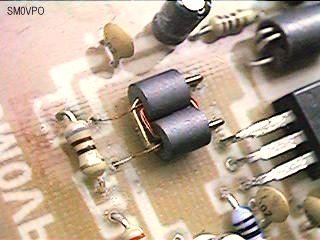
T1 - This is a simple transformer. Use 8-turns primary with a 1-turn secondary. The secondary wire should be quite thick but the primary can be as thin as you want. Wind on a 2-hole ferrite, or two ordinary ferrite beads placed side-by-side. This picture explains it all:
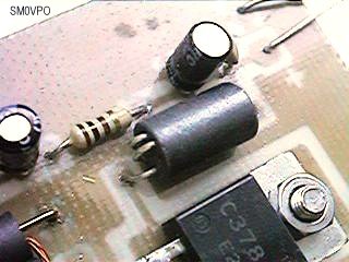
L1 - This is just any old inductor would on ferrite. The value is irrelevant. 2uH or mor work well, but I have used 5 turns 0.3mm Dia. wire on a ferrite bead. In the latest model I just pushed 0.5mm tinned-copper wire through 5 holes in a six-hole ferrite bead. Again, here is a photograph to explain everything:
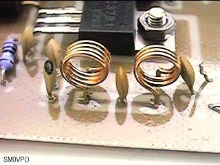
L2 and L3 are the only critical coils in the project. Use 0.5mm Dia. enamelled wire wound on a 5mm drill bit. L2 = 4-turns, and L3 = 3-turns. gain, here is a photograph to explain them:
No static sensitive components are used in the design of this project, so almost any component assembly order can be used. A good recommendation would be to fit all resistors first. All resistors are mounted horizontally on the board and have the lowest profile.
The next stage should include the ferrite bead inductors: T1, and L1. Fit capacitors, then the filter inductors, L2 and L3. TR1 and TR2 should really be fitted last, mainly because they are the largest components, but it is good practice to fit active components last.
TR1 should really be fitted with a heatsink, but a simple bit of thin tin-plate 1cm x 2cm shaped like "omega" (bent round a drill bit in the vise/vice) can be clipped on the transistor. TR2 did NOT need a heatsink on my prototype, since there is a load of copper under it, but if it has a tendency to cook then take a bit of tin-plate 2cm wide, 4cm long, bent at 90 degrees at 1.5cm and 2.5cm to form a "U" shape. This can be trapped under TR2, but drill a hole to pass the bolt through.
Before applying power, it would be wise to re-check the component values. Check that there are no shorts or solder blobs bridging adjacent tracks or pads. If all is well then power can be applied for the first time.
When building power amplifiers, small mistakes can often lead to quite spectacular pyrotechnic displays. The larger the amplifier then the more smoke potential the project can have. For this reason, all power amplifiers should be first powered with some form of current limiting power supply. If you do not have one, then wire a 12v 1A lamp bulb in series with the +12v supply line. If the lamp illuminates when the power is applied, then there is a fault, but the lamp will light instead of doing costly damage.
Connect the V5 transmitter RF signal to the input of the amplifier, and connect a suitable "dummy load" to the amplifier output. The RF connection to the V5 transmitter should be VERY SHORT and the two PCBs should ideally be touching each other with several tinned-coper wire straps between the groundplane copper of both boards.
A suitable dummy load would be an RF wattmeter with an impedance of 50 Ohms. If an RF wattmeter is not available then a 6v 0.6W bicycle lamp is suitable. Switch on the 12v DC supply to the amplifier.
You should see some RF power out. If you are using the bicycle lamp dummy-load then it should glow dimly. If not, then check for wiring errors. Check that adjacent turns are not shorting in any of the inductors. But if all is well and you have some RF power, then remove the 12v lamp and apply the full 12v. You should now get about 400mW of power (dummy load lamp at half brilliance).
One final check: remove the RF source and check that the 400mW RF out dissapears. Under certain conditions RF power amplifiers can "self-oscillate" (generate uncontrolled RF energy). Under this condition the output of such an amplifier will not be zero with no input. Self oscillation is caused by RF out fed back to the input, usually by magnetic or capcitive coupling. Components with excessively long leads can cause this. So, too, can certain wiring errors.
If the amplifier passes the self-oscillation test then it is safe to connect an antenna. Listen to the signal. The sound quality of the transmitter should be the same, whether or not the amplifier is connected.
This amplifier is an excellent companion to the low-power FM microphones in the 5mW to 10mW range. In addition to exercising basic soldering skills, it also introduces the builder to some simple RF tests and basic techniques for higher power projects. The circuit only needs the output filter components to be reduced in proportion (70%) for use in the 145MHz FM amateur radio band.
WARNING - 88 - 108MHz FM band transmitters are illegal to operate. This amplifier will increase the V5 FM transmitter to an illegal output power level. I have supplied the circuit in response to academic questions from visitors to my site (in an attempt to shut them up and stop sending me e-mail).
Range? - If you use a decent antenna, for example, the
Very best regards, and have fun, from Harry - SM0VPO