
This is yet another power inverter project, but this time it is designed to be the simplest power inverter you have ever seen. It is rock-solid stable, accurate frequency, and most of all, uses just six components, three of which are a zener diode voltage regulator. The other three components can generate 120 Watts of AC power at 50Hz (or 60Hz). You will of course need a transformer, but that is external to the board.
Around 2010/2011 I discovered the IRF510 power FET. These are lovely beasties. They will conduct current until they explode - the ON resistance is so low that you can comfortably drive them to 6 Amperes and without a heatsink. Many other devices have a significant resistance, which means a voltage drop. Voltage with current = power = heat.
Around the same period I discovered the 8-pin, 12-bit processors, such as 12F508, 12F509 and 12F675. They are childishly simple to program, especially if you have had any 8080, Z80 or 6502 assembly language experience. I have programmed all three.
Putting all these together I have created a new project for generating AC power.
The circuit is divided into two part:
Beginning with the voltage regulator, this is a 2K2 (2200 Ohms) resistor fed from the DC input, which drives an operating current through a 5.1 Volt Zener diode. A 220uf electrolytic capacitor is connected across the diode to remove any power supply glitches, spikes or Zener noise that may otherwise exist.
The 5.1 Volt regulator must be tested before the processor chip is plugged into the circuit, otherwise a wiring error could prove costly (US$2).
The processor GP0 (pin 7) and GP1 (pin 6) are connected to the Gates of the two IRF510 power FETs. The Source terminals of the FETs are grounded and the Drain terminals are connected to the transformer.
The microprocessor does everything and uses the internal 4 MHz oscillator so no other external components are needed. The IRF510 will be switched hard-ON or hard-OFF by the 5 Volts square-wave from the processor, so no voltage level or current buffering is needed.
An additional 0.1uF non-electrolytic capacitor is fitted to the board to stop any tendency to ringing, but since either TR1 or TR2 is always low-impedance the transformer is always well damped anyway.
The transformer can be a 230v (or 115v) to 12v-0v-12v type capable of handling 6 Amperes. This means a 60 Watt transformer. If you choose a torroidal type then the no-load standing current can be lower than 50mA :-)
You can alternatively choose a 230v (or 115v) to 24v-0v-24v transformer and get 120 Watts output. No other components need be changed at all.
The printed circuit board is (or will shortly be) given in the download section of these homepages, but please bear in mind that this is a first prototype board and it could be greatly improved. The large lands of copper were deliberately chosen to act as a heat-sink, but I ran the prototype for about 30 minutes at over 80 Watts continuous and the FETs remained stone-cold.
The 0.1uf safety capacitor must be rated at 2.5 times the DC supply voltage, that is 30 VDC for 12 volts input, or 60 VDC for 24 Volts input. The transistors are simply bolted to the boards without any of those insulation mica washers: just a pair of god-old M3 (or 6BA) bolts. Put two nuts on them and you can use the bolts as terminals for the transformer.
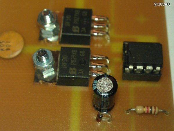
Note that the resistor I used in the prototype was 1K0 but for 24 Volts input it gets a bit warm. When I changed to 2K2 it was nice and cool. 2K2 provides the 15mA the 12F509 (IC1) requires.
You can easily extend the board by adding two extra transistors to give you 12 Ampere input current. This equates to 125 Watts at 12 Volts input, or 250 Watts output at 24 Volts input. I will be expanding the circuit board to include four FETs, but in principle there is no reasion why you cannot use more. 8 FETs (4 pairs), for example, will take 24 Amperes at 24V, which is over 500 Watts.
One small word of warning: I would strongly suggest the DC input and AC output be fused. If you overload this inverter then unlike many other designs it will simply NOT sag or sink. It will still push out power according to your demand until the output devices literally explode.
One BIG word of warning: the output of this unit can kill. Electrical shocks can be fatal. If you have no clue as to what you are doing, or if you have never used high-voltage circuits before then do not attempt this project.
Ok, this project uses software. I admit it! Guilty!! But I do appologize most profusely, although it is not really all that difficult. If you have a PIC programmer then you can download the HEX file and burn it yourself ising PICProg4U or WINPROG. I am using the MPLabs PIC-Kit2 programmer. A nice little programmer is published by Feng3, which you can download and use for free.
The HEX file you need is pic-inverter_02_code.hex, which you download and burn to the processor flash memory. Right-click the link and save the file to your hard disk.
If you want a chip ready programmed then you can contact me and I will see what I can do. Do not forget to state whether you want 50Hz or 60Hz.
If you wish to modify the code for your own application then you will need the source code. Here is my ASM file:
;************************************************************************
;                                                                       *
;   Filename:      50hz_generator.asm                                   *
;   Date:          2012-02-09                                           *
;   File Version:  1.0                                                  *
;                                                                       *
;   Author:        Harry Lythall                                        *
;                                                                       *
;************************************************************************
;                                                                       *
;   Architecture:  Baseline PIC                                         *
;   Processor:     12F508/509                                           *
;                                                                       *
;************************************************************************
;                                                                       *
;   Files required: none                                                *
;                                                                       *
;************************************************************************
;                                                                       *
;   Description:                                                        *
;                                                                       *
;   Toggles GP0 and GP1 at 50Hz in anti -phase                          *
;                                                                       *
;************************************************************************
;                                                                       *
;   Pin assignments:                                                    *
;       GP0 - Toggling                                                  *
;       GP1 - Toggling in oposition                                     *
;                                                                       *
;************************************************************************

    list        p=12F509
    #include

                ; ext reset, no code protect, no watchdog, 4Mhz int clock
    __CONFIG    _MCLRE_ON & _CP_OFF & _WDT_OFF & _IntRC_OSC


;***** VARIABLE DEFINITIONS
        UDATA
sGPIO   res 1                   ; shadow copy of GPIO
dc1     res 1                   ; delay loop counters
dc2     res 1


;************************************************************************
RESET   CODE    0x000           ; effective reset vector
        movwf   OSCCAL          ; update OSCCAL with factory cal value

start	movlw   b'111100'       ; configure GP1 + GP2 as an output
        tris    GPIO

;***** Change state of GP1 but leave GP0 as it is - set oposite status
        movf    sGPIO,w         ; get shadow copy of GPIO
        xorlw   b'000010'       ; flip bit corresponding to GP1 (bit 1)
        movwf   GPIO            ; write to GPIO
        movwf   sGPIO           ; and update shadow copy

;***** Main loop
flash   movf    sGPIO,w         ; get shadow copy of GPIO
        xorlw   b'000011'       ; toggle GP1 + GP2
        movwf   GPIO            ; write to GPIO
        movwf   sGPIO           ; and update shadow copy

;***** delays
	movlw   .10		; outer loop: N x 1mS (default .10)
        movwf   dc2             ; = 1/2 cycle

time	movlw	.245		; inner loop: = 245 for 50 Hz    <== Frequency adjustment
        movwf   dc1             ; (with correction factor)

dly1    nop
        decfsz  dc1,f
        goto    dly1
dly2    nop			; inner loop = 1ms
	decfsz  dc2,f
        goto    time		; reset dc1 to default value
        goto    flash           ; repeat forever

        END
Note that the subroutine line "time" has two options for frequency adjustment. If you assemble the file as it is then you will get 50Hz, but swap the 245 value for 204 and you will get 60Hz. You can also measure the inverter frequency over a period of time and alter this value. You can increase or decrease the inverter frequency in about +/-0.2Hz steps.
The loop "dly1" has a delay of 1mS and this is inside a 10x loop to give 10mS delay. The output port status is changed and the delay loop called again. To get 60Hz output the 10mS loop is changed to 8.33mS. The high value of 245 here is close to the maximum allowed (255) so gives the smallest increments for frequency adjustments.
You may notice that I use the shadow GPIO method, even though I do not use any read functions for the output ports. This has become a sort of regular thing for me since I started learning about PIC programming. This program, however, has not changed much since I used the "hello world" LED tutorial from Gooligum Electronics (Australia) tutorials.
As a matter of interest, the IRF510 will operate into the VHF region, which means that you can screw the frequency of this little inverter up to a few 10s of kHz for a more efficient converter. If you needed to get 250vDC for a valve (tube) project then this would be ideal and with only a miniature SMPSU ferrite transformer.
If you have any technical questions then I try to answer all e-mail questions, but I would prefer you used my messageboard for technical queries and discussions. There are many people more clever than me using the board.
Unfortunately I cannot offer this project in kit form because I cannot make quality PCBs any more. I am almost blind in my right eye due to cataracts, but I hope to have a new glass lens fitted later on in the year. It is not life-threatening so the priority for the Swedish medical service is low. But it makes soldering and drilling very difficult for me.
These projects are all 100% free for non-profit private use. You may download and use privately all my projects, PCB foil patterns and software. These projects have taken years to create and are free from membership, advertising and banners.
Best regards from Harry - SM0VPO
Return to INFO page