
For some months I have been nursing the thought of making a "universal receiver": a receiver that can be used from DC to light, or something like that. The idea was to make a receiver using the TDA7000 receiver chip, and changing the components for either WBFM or NBFM. If the TDA7000 receiver is used at, say, 5MHz, then by adding a harmonic converter the complete receiver could be used to tune from 1MHz to perhaps 200MHz.
I had hoped to get almost crystal stability, with VFO capability.
Unfortunately the TDA7000 has a few disadvantages, and behaves more like a little toy project. I have always felt that the chip may feel a little more stable and become a little more sensitive at lower frequencies, but I was wrong. Here I shall present my findings for your own education, or perhaps for you to correct my mistakes. But as far as I am concerned, the TDA7000 chip is a toy. It works fine for WBFM in the 88MHz - 108MHz range, although the sensitivity is a little lacking.
I also found out that the Philips recommendations of a 5kHz IF for NBFM is also a little bit optimistic. 5kHz breaks through to the output audio and requires at least a fourth-order filter to clean it all up. I took the IF up to 10kHz and was able to get a more reasonable result, although the sensitivity is still not very good.
The receiver uses a crystal oscillator in a configuration that will oscillate at the crystal fundamental, or odd harmonics. Having said that, I managed to get it to operate at the 6th harmonic of a crystal designed for operation at it's 3rd harmonic. The crystal was 70MHz, ripped from a crystal filter. In this project I shall use that crystal, but at the fundamental frequency of 23.33MHz.
The oscillator is coupled into a dual-gate FET (BF981), together with a single tuned-circuit antenna pre-selector. The drain of the FET is tuned to 4-6MHz so the complete receiver will tune the 27MHz - 29MHz bands. This is ideal for 10m FM, CB, or even the R/C bands.
The TDA7000 chip is tuned to 4MHz - 6MHz by the single oscillator coil, L1, which gives excellent frequency stability for these low frequencies. This gives the complete receiver a crystal-controlled stability, but with VFO capability.
The BF981 converter has a conversion gain of about 20dB at 28MHz, and is perhaps the only redeeming feature of the whole project. If you want to make yourself a nice 4m or 2m receive converter then this is the circuit to use. But I added the TDA7000 chip, and it does work to receive NBFM.
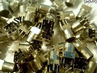
Yes, there are coils! Lots of them, and all wound on salvaged IF cans. Perhaps this is also another redeeming feature of this project, the re-use of coil formers. Thanks to a good friend, I received a few hundred of these 7mm cans. There were a huge mixture of different cans, all pre-wound for various projects. These I take apart and re-wind to suit my own needs. I then re-wind them so that I have custom coils. It is a bit of a pain to begin with, but I do find it fun. But I will cover this in more detail later on in the project.
T1, T2, T3, and L1 are preset slug-tuned coils, which can be varied by about 10% from the nominal frequencies quoted. There may be some variation, depending on the type of can you re-wind, so some experimentation may be required. L1 = T3. The value of C and each coil is given in the tables below.

For 28MHz, T1 (antenna pre-select) has a 12-turn, centre-tapped (6 turns + 6 turns) tuned winding, and the antenna is coupled in via a 1-turn link. All five pins of the coil former are used. The coil is brought to resonance by a 15pf NPO capacitor. You can select the capacitor to cover other frequencies, without rewinding the coil. 30pf will get you down to about 20MHz, and 3.9pf will get you up to 60MHz. Beyond these limits you should re-wind the coil. Note that the centre-tap is grounded. This helps the overall stability of the project.
For 23MHz, T2 (oscillator tuning) has a 12-turn tapped coil (3 turns + 9 turns) for the tuned winding, and a 4-turn link to feed Gate 2 of the FET. The primary centre-tap is connected to the supply +ve, the 9-turn end is coupled to the transistor collector, and the 3-turn end has a low-level and inverted output that feeds the oscillator transistor base. Connect to the base via a 10pf capacitor and it will begin free-running, so you can experiment with frequency. Replace the capacitor with a crystal and it will only oscillate a frequency dictated by the crystal. T2 is brought to resonance with an 18pf NPO capacitor. Again, this inductor can operate from 18MHz to 50MHz by changing the tuning capacitor from 39pf to 4.7pf. Beyond this range you need to re-wind the coil.
For 5MHz, T3, and L1 (mixer output tuning and TDA7000 oscillator) have a 24-turn centre-tapped (12 turns + 12 turns) tuned winding, brought to resonance with a 100pf NPO capacitor. The secondary winding from T3 feeding the 50-Ohm input of the TDA7000 is 4-turns. The centre-tap of the primary is the supply voltage. This technique aids stability. The oscillator coil, L1, does not need a centre-tap or secondary link, but I included them so that the coils can be inter-changed: why have two different types?
As a simple rough coil-winding guide, here are suggested coil-winding data for different frequencies. As stated, you may find some differences, depending upon the surplus cans you are ripping apart.
| Typical Coil-Winding Data | ||||||
|---|---|---|---|---|---|---|
| Band | T1 (Ant) | T2 (Osc) | T3 (Mix) | |||
| Freq (capacitor) | Tune (turns) | Ant (turns) | Tune (turns) | Tap (turns) | Tune (turns) | Out (turns) |
| 2.5MHz (220pf) | 50 (25 + 25) | 8 | 50 (10 + 40) | 10 | 50 (25 + 25) | 8 |
| 5.0MHz (100pf) | 24 (25 + 25) | 4 | 24 (4 + 20) | 7 | 24 (12 + 12) | 4 |
| 10MHz (47pf) | 16 (8 + 8) | 3 | 16 (4 + 12) | 5 | 16 (8 + 8) | 3 |
| 20MHz (22pf) | 14 (7 + 7) | 2 | 14 (3 + 11) | 4 | 14 (7 + 7) | 2 |
| 30MHz (15pf) | 12 (6 + 6) | 1 | 12 (3 + 9) | 4 | 12 (6 + 6) | 2 |
| 50MHz (8.2pf) | 8 (4 + 4) | 1 | 8 (2 + 6) | 3 | 8 (4 + 4) | 1 |
| 100MHz (4.7pf) | 4 (2 + 2) | 1 | 4 (1 + 3) | 2 | 4 (2 + 2) | 1 |
I also found that of all the types of can I dissassembled, there were basically two types: One had a big, fat core that had a far greater diameter than the others. The core bobbin was also longer. This former gave a little more inductance than the smaller types, so I chose these smaller formers for this project. The former size affected the coil data by about 20%, so beware. I suggest you wind a sample coil on your former, test it, and scale the rest of the coils the same. Alternatively you can stick to my turns table, but scale the capacitors. Above 100MHz I cut away the ferrite bobbin and fitted a plastic bobbin in it's place.
As as I wrote at the outset, the 5kHz IF recommended by Philips was found to be quite impractical, so I adjusted the capacitor values a little to center the IF on 10kHz. This still allows the receiver to give a reasonable output with +/-2.5kHz deviation (NBFM). Excessive deviation causes the MUTE circuit to close the receiver. There is no reason why you should use this project for WBFM, except perhaps to have a more stable receiver. But here are the capacitor values. I have indluded the Philips recommended values, just in case you want to have a fiddle.
| Table of TDA7000 Capacitor Values | |||
|---|---|---|---|
| Capacitor | WBFM (IF=70kHz) | NBFM (IF=10kHz) | NBFM (IF=5kHz) |
| C1 | 150n | 150n | 150n |
| C2 | 1n8 | 100n | 2n7 |
| C3 | 22n | - | - |
| C4 | 10n | 4n7 | 4n7 |
| C5 | 10n | 100n | 100n |
| C6 | - | - | - |
| C7 | 47n | 100n | 100n |
| C8 | 330p | 2n2 | 2n2 |
| C10 | 10n | 100n | 4n7 |
| C11 | 3n3 | 47n | 100n |
| C12 | 150p | 2n2 | 3n3 |
| C13 | 2n2 | 1n0 | 1n0 |
| C14 | 10n | 1n0 | 1n0 |
| C15 | 100n | 10u | 4u7 |
| C17 | 330p | 2n2 | 4n7 |
| C18 | 220p | 2n2 | 2n9 |
Note that C6, C9, and C16 do not exist because the capacitor numbers have been chosen to follow the TDA7000 pin numbers. The middle column above is the one I used to get the project working. C3 has been omitted to disable the internal noise generator, to give "silent tuning".
Here is the finished prototype. There is (or will be, soon) a PCB foil patern available for you to download. I have incorporated some of the "hacking" I did on the board to suite the components I had available. For example, 0.1uf (100nf) ceramic caps are better fitted with 5mm hole-spacing, but all the rest I used 2.5mm. I also added an LED squelch indicator, driven from pin 1 of the TDA7000, but that is not in the picture above.
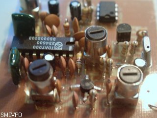
According to the specification, the chip sensitivity is about 3uV EMF, but I was not able to duplicate this, even with 20dB of gain in the RF converter. I found that the sensitivity was more like 40uV, direct into the chip, and about 10uV with the converter in circuit. I also fitted two back-to-back "zero-bias shotky diodes" across the TDA7000 input, and this considerably improved the high-level signal-handling characteristics of the receiver. These have not been incorporated on the PCB.
AF distortion was something else. With the 5kHz IF I could hear that annoying heterodyne at all settings of tuning. It was not even possible to push the RX to the high-IF side to get rid of it. I had to use a couple of external OpAmp, 2nd order filters, cascaded, to get the level down to an acceptable level. But by raising the IF to 10kHz I found that simply changing C2 to 100nf caused a drop in AF level, but the quality was quite acceptable for the human ear, without additional filtering.
Overall, the project was not as good as I thought it could be, but the re-use of IF cans, and the front-end frequency-converter made the whole project worthwhile. If you do not build the complete receiver, then the converter and coils may be a good exercise. That is why in the next section I shall devote a lot of photography to the re-use of IF cans.
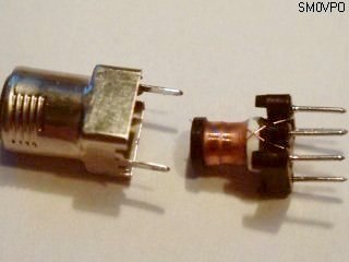
As I mentioned earlier, a very good friend gave me a load of surplus (unused) IF cans. They were almost all 7mm cans, but internally there were about 5 different types. These cans are ideal for rewinding PROVIDING you have a little patience. Nearly all the ones I have are single-coil types, some intended for LF use. In all cases I removed the existing winding. To take the cans apart, use an instrument screwdriver to gently lift the tabs holding the metal can over the former. The former can be gently pulled out.
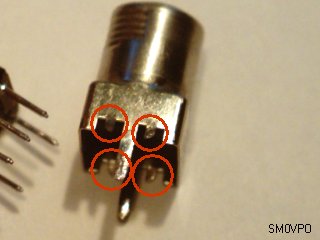
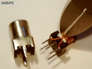
Straighten the tabs to make it easier to re-assemble the former when it has been re-wound, but be careful not to damage the ferrite slug. The side wall/apron inside the can is very thin and fragile. For some reason, all coils were wound in the same direction, so identify the upper-most end of the coil, and clip it. Gently heating the pin with a soldering iron will allow you to unwind the end of the wire from the leg of the former. Here I have highlighted the wires. They cross over, but you can identify the upper wire to cut.
Unwind the wire from the coil so as not to break the wire. If you loose the end then it can be a heck of a job to get all the wire off. When you get to the end of the coil, use the iron to melt the solder and unwind the end of the wire from the other former leg. Now you should have a nice coil former, ready for re-winding.
The bobbin is made of ferrite, and the slug in the can is screwed over the bobbin to increase the inductance. If you want a coil for 50MHz to 200MHz range then you can break the glue that holds the ferrite bobbin to the former base. Now you can super-clue (crazy-glue, cyanoacrylic adhesive) a plastic bobbin back in it's place. A suitable bobbin is a bit of the inner tube from a ballpoint pen (before the ink starts). I have also succeeded drilling a 2mm Dia. hold down the center of one former base and fitting a 2mm plastic bolt - cut off to a suitable length, but this takes a bit of practice.
When fitting new turns, tin the ends of the wire, and wrap at least 2 turns around the leg before soldering. You should also use the precision screwdrivers to press the two turns as close to the plastic former base as possible. The "thin" wire needed to re-wind the coils on the micro bobbins was robbed from high-resistance relays.
If you are lucky enough to get a load of coils with in-built capacitors, then test them first. It may be that the coil is usefull without modification, perhaps in another project.
To test the coils, you can couple the parallel tuning capacitor in series with the coil, and use the spectrum analyser / tracking generator to see the resonance point. Failing this, you can fit the tuning capacitor external to the coil, with long leads, and use the loop so formed with the GDO to a signal generator, and watch the output from the tuned winding on your oscilloscope VIA A 10K RESISTOR. Note that you cannot connect any test equipment directly to the tuned winding without de-tuning the circuit.
As a receiver project you would be well advised to use the TBA120S as an FM IF sub-system. I do (will shortly) have this project on my homepages, complete with a PCB foil pattern. But for coil-winding and RF converter, this is a nice project and is a good starting point for further experimenting. If you have also had a hankering to try using the TDA7000 for NBFM, or perhaps have masochistic tendencies, then perhaps you may be able to "tame the beast". I cannot be bothered, but it was worth a try.
The TDA7000 is a lovely little chip for receiving WBFM broadcast stations, albeit a little insensitive. Amy Diamond and Dogilito sound just as fine, so AF distortion is not a problem. But as an NBFM receiver it only makes a poor paperweight. It does, however, remain quite still when I took the photograph, so there is something to be said for it. For me, the success of this design was the RF converter and the re-wound coils. I have re-wound coils before, but here you can see the technique in greater detail.
Very best regards, and most of all, have fun.
Return to INFO page