
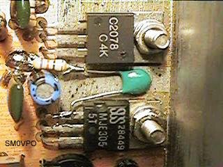
It is quite easy to get a watt or more with very simple equipment, but to get more than 5 watts becomes a little more difficult. This article describes a 10 watt linear amplifier that is capable of delivering over 15 watts into 50 ohms and uses cheap plastic transistors that are used in CB equipment. If you have difficulty in finding 2SC2078 then lift the lid of your CB set to find a suitable alternative. The bias generator transistor, TR4, is marked TIP31 in the circuit diagram, but here you can use just about anything that will fit. You could even use another 2SC2078, if you had money to burn, but more practical components would be TIP41, TIP3055, MJE3055. All that matters is that it will pass up to 1 Ampere and have the correct base details in a TO220 case.
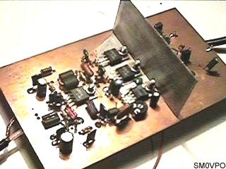
The amplifier has a wide bandwidth, from 1.8 MHz through to over 30 MHz. The drive level required is only about 2 - 5 mW under 14 MHz, rising to 10 mW at 30 MHz. You can therefore make a good QRP CW rig with nothing more than this PA and a simple crystal oscillator. I can achieve 12 watts out of mine using a 10-turn loop around my Grid Dip Oscillator! I can get over 15 watts from my Marconi signal generator, but above about 12 watts it is being over-driven an may not be very nice to look at on the spectrum analyser. The circuit was designed to be as clean as possible. Here is a view over the completed PCB (sorry the photo is so crappy):
The circuit was originally designed to accompany my phasing-type SSB exciter, but it can be used to amplify almost any HF signal from 2mW in the HF band. Note that there is needed a Low-Pass filter between the amplifier and antenna. This is a requirement for ALL transmitters.
L1 matches a 50-Ohm input to the 10-Ohm input impedance of TR1. The output of TR1 is coupled via T1 to TR2 and TR3 bases. T1 also transforms the impedance to the very low input impedance of these two transistors, so the secondary winding must be quite thick wire.
TR2 and TR3 amplify the signal even further, up to about 12-Watts. They are in a push-pull configuration so T1 secondary and T2 primary must both be symetrical. T2 increases the output impedance to 50-Ohms.
TR1, TR2 and TR3 all have a 330R and 10n between the collector and base terminals. This is needed for stability and is a crude form of neutralising. Without these components then the stages would almost certainly oscillate or generate spurious signals. An additional 180pf capacitor from both TR2 and TR3 collectors to ground (not shown in the circuit diagram) give the amplifier an even cleaner output signal. The 68pf capacitor across the output may be increased if you never use the 30MHz band. It, too, increases the stability and helps to keep the harmonic content low. My spectrum analyser did not show any significant spurious or harmonic outputs from 0 - 100MHz when driven at 10-watts continuous, 14MHz. All spurious outputs were better than -60dBm (-70dBc), which I though was pretty good!
TR4 is nothing more than a high-current constant voltage series regulator using a 3v3 Zener diode for stability. It provides the base-bias voltage for TR2 and TR3. The 1K thermistor is thermally coupled to the tinned-copper heatsink to reduce the bias a little when the PA gets hot. More about the thermistor later.
To align, set the 1K0 potentiometer to minimum resistance, apply power to the 'PA-12v' and 'DV-12v' terminals whilst monitoring the current drawn by the 'PA-12v' connection. The current should be next to nothing. Increase the potentiometer until the current rises to about 50 - 100 mA. That's it!
I invariably receive loads of e-mail asking me all about the coils I use. "What was the relative humidity when you wound ..." and "I don't understand what a ferrite bead looks like ...". Ok, so to answer your questions:
L1 is 6 + 6 turns 28 - 36 SWG wire on two "small" ferrite beads super-glued together - side-by-side. The two windings are connected in series to form a single 12-turn coil with a centre-tap. The two ends of the coil are input to the amplifier and ground. The centre-tap is connected to TR1 BASE via a capacitor.
L2, L3, L4 are all about 10 turns 28 - 36 SWG wire on a single ferrite bead. If you use thick wire then only 4 or 5 turns will do. You just can see one of the coils in the above picture (top). L5 is just an 18 SWG link fed through a ferrite bead. If you have a bead with a hole big enough to take a turn or two then by all means add a few turns (it just makes the hammer that bit bigger when smashing eggs).
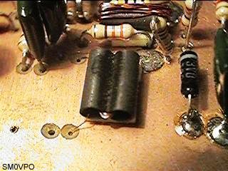
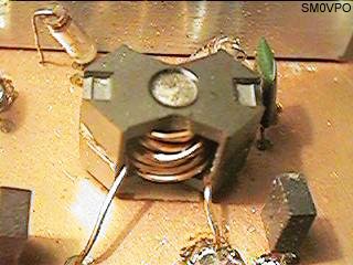
T1 is 6 turns 24 SWG wire on two large ferrite beads superglued together - side - by side like a pair of binoculars. Use larger beads for this, I used two large ferrite slugs (8mm Dia.) robbed from an old valve IF can. The secondary that feeds the final amplifier pair are 1 + 1 turn 18SWG enamelled wire. It looks like this:
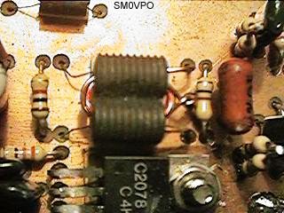
T2 has always given people a lot of problems. It is just 3 + 3 turns 18SWG wire on a large twin-hole ferrite slab or even a "Pot-core", as I have used. All work equally well. The secondary winding is 16 turns 22 SWG. It is not the material that matters, but the physical size of the ferrite. If the ferrite gets hot then it is too small. You could stack 2 or 3 1/2" ferrite rings on top of eack other - twice, then place the 2 tubes formed side-by-side to form another binocular ferrite shape, all held together with superglue. Here is the last T2 I used, and the one I shall continue to use.
The thermister is connected between the BASE of TR4 and the copper ground- plane on the top-side of the PCB. It's purpose is to reduce the bias voltage to TR2 and TR4 when they heat up a little. This reduces the standing (no-signal) current to the original setting and prevents "thermal stroll-away" (it begins slowly). In my case I used a 1K0 thermister in series with a 330R resistor. The 330R resistor damps the effect of the thermistor by lowering it's dynamic range. The thermistor is placed in direct contact with the tinned-copper heatsink for the power transistors. If you have problems with the idle current (no signal) whether hot/cold, then reducing the 330R and reseting the bias current will lower the "hot PA current". Increasing the 330R will increase the "hot PA current". The PA standing current should be the same, no-matter whether TR2 and TR3 are hot or cold.
The PCB is constructed on double-sided copper-clad board, but only one side is etched. During assembly, insert each component with reference to the component overlay. If there is a red circle with a green cross over a hole, then the component lead must be soldered both top and bottom. If there is no cross/circle then the top-copper should be countersunk a little with a 3mm drill bit to remove copper from the edge of the hole. This is clearly shown in this picture:
The decoupling capacitors in the circuit are somewhat "diagramatic". I really used the first cap I put my hands on, and there are only two types of decoupling capacitors; BIG ONES and small ones:
| BIG - An electrolytic somewhere between 10uf and 10,000uf |
| small - A ceramic cap somewhere between 1nf and 330nf |
I was fortunate enough to get my hands on a load of ultra-miniature low-voltage electrolytics in a rectangular plastic case. Use whatever you have got to hand, it is all the same and the decoupling component values are all VERY FLEXIBLE. You will notice that in the circuit I show the places that must be decoupled, but on the real board there are quite a few more. You cannot really have enough decoupling. I love it!
A PCB foil drawing is available. Sorry about the quality, but I drew it around the year 5BC (5 years Before Computers). At that time I used pens and drafting film to draw all my circuits. Download the PCB foil for the ten watt PA (38,712 bytes). The size of the copper foil is 134mm x 72mm, but I also have about 1cm extra as a border all the way ariound the board for mounting the complete PCB.
The last point is that the heatsink is made of 0.5mm tinned copper plate, bent into an L shape so that it fits under the three power transistors. I have shaded the bottom of the L in red on the component overlay. The vertical part of the L is connected to a much larger aluminium heatsink, for example, the metal case of your transmitter.
Have fun, from Harry SM0VPO, Lunda, Sweden.