
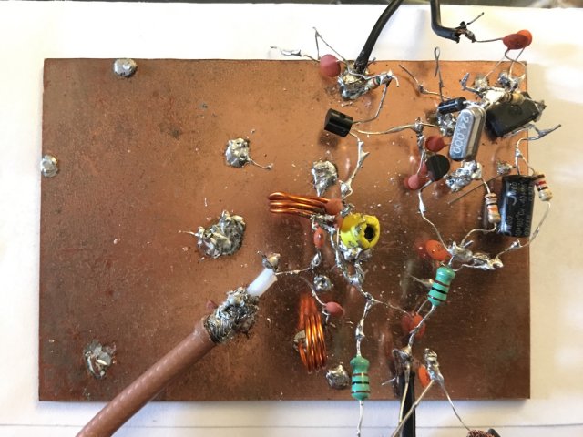
I sometimes see really beautifully-built projects, with computer-laid out printed circuit boards. But when it comes to RF work, it is very difficult to meet the performance of the "ugly-bug" (dead-bug) method of construction, soldered on a layer of copper-clad PCB material. The result invariably look makeshift, but the results are usually surprisingly good when RF is involved.
Joy Mukherji, from my messageboard, supplied information for a 96MHz FM transmitter project, which I feel is of particular interest for both performance and the method of construction. Here is Joy's project including his pictures and technical description.
Hi Harry,
Here are the final images and text description for the 96MHz FM TX.
The crystal locked FM transmitter presented here avoids the use of a LC tuned tank circuit or complex PLL (phase locked loop) method for FM carrier generation. Instead it uses a fixed frequency crystal and IN4007 as varactor diode. The 24 MHz crystal frequency is quadrupled for a final transmit frequency of 96 MHz. The audio fidelity is surprisingly good.
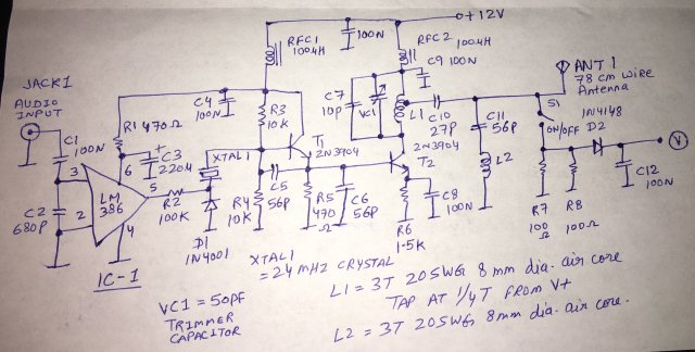
A 50-Ohms level is taken off at 1/4 turn from top of the collector tuning coil and coupled to a 78cm long wire antenna for transmission. The signal can be picked up by an FM receiver tuned to 96 MHz.
The audio amplifier built around IC1 has a gain of 20. R1 and C3 removes noise and suppresses IC1’s tendency to self-oscillate. The amplified audio from the LM386 frequency modulates the oscillator by varying the capacitance of diode D1 which is connected in series with XTAL1. No hard to find varactor diode has been used. The IN4007 gives good performance. C2 prevents RF from getting into IC1. The trasmitter accepts audio input from an external equipment, such as a computer, music player, or your mobile phone. The external volume level should be set for best audio quality without distortion.
Keep all leads short. It is a standard practice at RF and aids in stability. The prototype was built on a piece of copper clad board using ugly bug construction method. Apply 12V power from a SMPS regulated power supply. Turn on S1 and tune VC1 for voltage reading at the point marked as ‘V’. It should be around 130mV. Carefully tune the 50 pf trimmer capacitor for the highest peak reading. All unwanted harmonics are now down below -24 dBc or more. A spectrum analyser may be used to confirm that the fourth harmonic has been boosted. If you don't have access to a spectrum analyser then the correct tuning of VC1 can be confirmed by connecting a wire antenna and testing for maximum range on an handheld FM receiver by walking away from the transmitter. Correct tuning of VC1 will give maximum range on 96MHz. L1 and L2 are 90nH air core inductors.
Turn off S1 and connect a 78cm wire antenna. Use shielded cable for input audio connection. The current consumption of the transmitter is 20ma and delivers an RF power output of +6dBm (4mW) which is more than adequate to cover my two bedroom apartment with good signal strength. An external VHF amplifier may be used to boost the power output to several hundred milliwatts along with a matched ground plane or dipole antenna for 1Km range.
L1 = 3T 20SWG enamelled copper wire wound on 8mm diameter air core. Tap at 1/4 turn from V+
L2 = 3T 20SWG enamelled copper wire wound on 8mm diameter air core.
Variable trimmer capacitor = 50 pF (12-66pf variable)
100uH RFCs used are readymade moulded chokes to isolate the oscillator and buffer stage and help reduce unwanted harmonic content at the output. L1 and L2 are 2cm apart and 90 degrees to each other. This arrangement gives the best harmonic suppression. A low pass filter with a cut-off frequency of 110MHz may be used to further clean up the output signal.
![]()
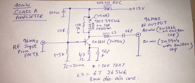
Joy has also developed a 40mW Power Amplifier stage for this project. Joy wrote:
Hello Harry,
Please include this 2n3866 based amplifier in my 96MHz FMTX article.
I added a 2n3866 based class A amplifier to raise the output power to +16dBm or 40mW. It increased the range to 200 meters with the transmitter lying indoors. The output was loaded into a 470ohm resistor to protect the transistor and a 78cm long wire antenna was connected for testing. The 470ohm resistor should be removed when feeding a properly matched antenna (ground plane or Harry’s VHF J-pole antenna).
The 56pF emitter capacitor increased the gain and output power to 80mW but amplifier was self oscillating so it was removed. A 2n3904 can be substituted in place of 2n3866 but the output will fall to +13dBm (20mW) or so. The 56pF emitter capacitor can be used with 2n3904 without a problem. The plastic case of 2n3904 needs to be superglued to the copper clad board to keep it cool. The 2n3866 gave a cleaner output of 40mW and did not require a heatsink so I recommend the 2n3866 for its superior performance. Do not use emitter capacitor with 2n3866 to keep it stable.
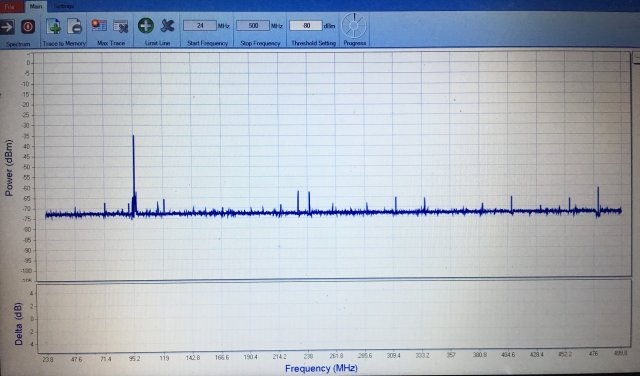
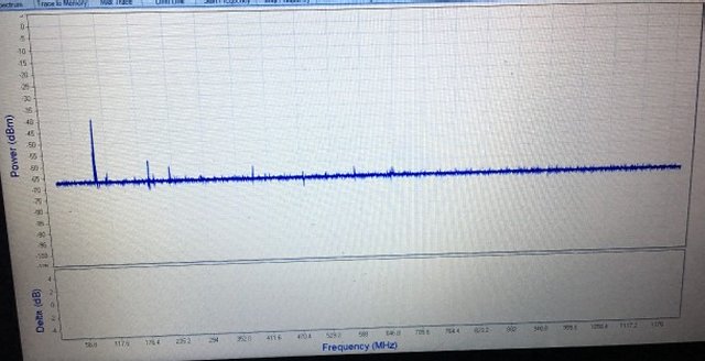
Attached is the spectrum output of the 40mW 2n3866 amplifier from 24MHz to 1.2GHz. Second and third harmonics of 96MHz are -18dBc and -25dBc respectively.
I want to thank Joy for his useful contribution to the visitors circuits. A project like this is very useful to show a working method of construction that is cheap, quick and gives excellent results.
Don't forget to visit my messageboard. If you have any questions about this project then ask on my messageboard, or e-mail Joy.
Very best regards from Harry Lythall
SM0VPO, Märsta, Sweden.