
I was made redundant as from the 31st of December, 2023. So now, at 72 years, I am retired. I am starting to play "catchup" (not ketchup) with some of the projects I never had time for. In 2023 I did work on projects that were not documented. One of them is an FM transmitter that required a few odd-ball capacitors, for example 3.647pf. It needs very special capacitor values because it is an elyptic filter, having responses at specific frequencies. This makes it extremely difficult to get the exact values needed. This the circuit I am building:
I made the PCB to accept two capacitors for each value, so that you can insert a combination of two using standard values. 1pf plus 2.7pf = 3.7pf, which is close enough to 3.647pf. But would it not be nice if you could adjust the value of a standard NPO ceramic capacitor? Well, you can. read on.
I did not have any standard values lower than 10pf, so I thought about it. Why not cut the capacitor in half? Take a look at a typical ceramic capcitor. From the side it is simply a disk with two wires attached and encapsulated to protect it from the elements (and dirty constructors fingers). From above it can look something like this:
Take a nice sharp pair of wire cutters cut off the top half. If you do this then a 10pf will become about 5pf. If you want a small decrease, then clip off less than 50%. If you want an exact value, then you can take a cheap ladies nailfile (that is not a cheap ladies file, but a ladies cheap nailfile. Sorry!). Now you can file a bit more off to get to the exact value you want.
Remember that you can always cut a bit more off, but you cannot put it back, so start with the capacitors having the highest values. If you file off a bit too much and the value is lower than you want, then continue filing to get the next value on your list. Cheap nailfiles have something like 4 or 6 different grades of roughness, from ripping fingernails out, to about as soft and effective as toilet paper. These are perfect for this job.
Calibrating the capacitor is far easier than you would think. I used a 10k resistor in series with a tuned circuit. The coil I used was 3 turns of 0.8 mm diameter enamelled copper wire, close-wound on a 6 mm drill bit. The coil will spring open about 0.5 mm when you stop winding. Keep the leads as short as possible, typically 5 mm. This has an inductance of 0.099µH. Using the basic formula, 0.099µH and 3.647pf will have a resonant frequency of 264.8MHz. The 10KΩ resistor is to be sure that you only measure the tuned circuit response without any other form of loading.
If you do not have a spectrum analyser with a tracking generator, then you can use a 1-turn loop on the coil of a Grid-Dip Oscillator (GDO), and view the RF on an oscilloscope. I tested this with a 100MHz scope. The oscilloscope frequency response does not matter at all, you do not need it to be calibrated. You only need to see the sharp dip when the generator passes through resonance. If necessary then you can use a larger coil to get a lower test frequency.
If you have an analyser then this is a typical response curve. If you know what it looks like then you will know how to find it using the GDO and oscilloscope.
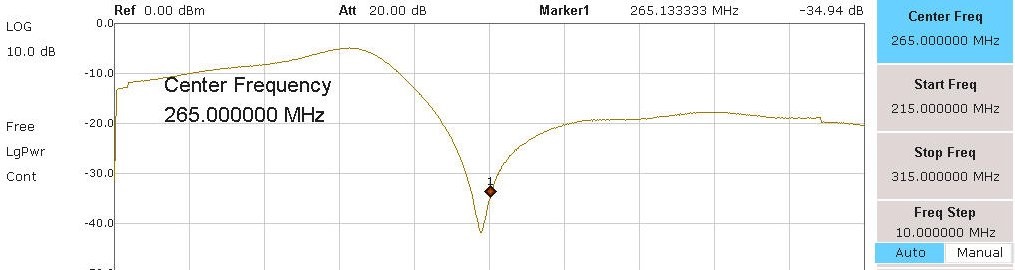
When the capacitor is mounted on the PCB the wire leads clipped off will reduce the capacitance a bit. Leaving the frequency just a tad low is good. When you check the final filter ou can always trim the response if it is needed. Remember that the formula for frequency used the square-root of capacitance, which means the effects of stray capacitances are smaller than the capacitance changes: if the capacitance error is 10% then the resultant frequency error will be only 3%.
When you have finished then the capacitor will loook like this:
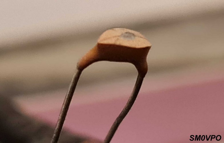
When the capacitor has been finally trimmed in circuit, then a small dab of cheap ladies nail varnish will seal it (I did it again, I mean cheap ladies varnish, but not the varnish from a cheap lady. Sorry!). The elyptic filter section of the finished transmitter looks like this. Note that the coils have been trimmed using the same test circuit.
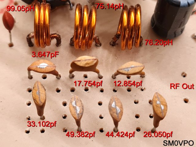
It is worth noting that I chose one inductor as a reference (L1 - 99.05pH) and adjusted ALL the capacitors using this as a reference. The winding details I took from my coil winding data. I then took one adjusted capacitor and used that as a reference for adjusting the inductors. If the coil has an error of, say 3%, then ALL components will have the same error, but the proportions of the values will be as close as you calibrate. That is to say that the values are all relative and so any error will be negated .
In the above picture you can see that the coils aere all clost (3 turns) but I adjusted the spacing a little to get them exact. I did select a 10pf when I wound L1, just to be 100% sure that the calculations were correct. When adjusting the components you need to have access to the two relevant calculators. L1 (reference inductor) 99.05pH in the test circuit, with 33.102pf will give a dip on the analyser at 87 895 324.63906682 Hz (87.8953 MHz).
Formula: Frequency (F) = 1 / (2 * Pi * Sqrt(LC))
I hope that this project has given you some "food for thought". You can always e-mail me at harry.lythall@[my domain].com. You can even use oeieio@hotmail.com or hotmail@sm0vpo.com as they are both valid e-mail accounts for me 😉 although I would prefer that you visit my messageboard if you have any questions about this or any other project. I always look forward to receiving feedback, positive or negative 🙂
Very best regards from Harry Lythall