
I have built a valve GDO in the late 60's, but today I use a smaller unit based upon a BF245 Field Effect Transistor. In reality it is a Drain Dip Oscillator. Whilst I was working in Saudi Arabia I built several of these instruments & assisted 14 of my tech's to build their own. In doing so I also learned a few new tricks as the Phillipino technicians in my workshop were very inventive.
Here is the circuit of the unit, which is based upon a Wheatstone bridge circuit; the oscillator being one resistor of the bridge. This technique greatly improves the depth of the dip observed. The battery is a simple "PP3" 9v battery, which will last a year (or more) in this application. For this reason I soldered the battery terminals instead of using battery clips.
The transistor can be almost any FET. For example, BF245, 2N3819, TIS88, J310, etc. There is absolutely no reason why you cannot use a dual-gate FET, but connect G2 to a voltage divider (4.5v from the battery). G2 can then be used as a "Modulation IN" terminal.
The meter is a cheap 100uA unit robbed out of an old stereo radio. The tuning capacitor is also robbed out of the same radio. The radio had VHF FM and MW AM, so the tuning capacitor had 4 capacitors, 2 x 270pf (C2a + C2b) and 2 x 20pf (C2c + C2d). All four capacitors are used in this circuit.
Coils are plug-in type using a 5-pin DIN socket on the GDO unit. The coils are centre-tapped and wound upon coloured plastic formers robbed from those cheap childrens felt-tipped colouring pens. Old credit-card plastic sheet was used to make formers for the larger coils by cutting out a 2cm disk with a 1cm hole for the pen-tube. Three disks are used for each coil. Each coil is connected to the 5-pin DIN plug pins 2, 4 and 5. This selects the smallest tuning capacitors, C2c and C2d. Short together pins 1-4 and 3-5 on the coil plug to select the larger tuning capacitor for the lower frequency bands (above 50 MHz).
"Thin" wire I used was robbed from a low voltage relay. I am not sure what guage it was, but it is "pretty thin" (C:A 40 SWG - ish!!). All coil windings and formers were "tacked" in place with super-glue then "gunged up" with epoxy resin (Areldite) after testing. Fix formers to the DIN plug using more epoxy. I passed all coil wires down the inside of the formers and poured a little epoxy down the inside to set every-thing solid. The majority of the former was left hollow so that I can stuff coils inside it for VERY close coupling. You may have to "play" with the coils a little to get the correct coverage.
Mount the tuning capacitor about 1cm above centre of an aluminium box, 8cm x 6cm by about 3cm deep. Connect the four tuning capacitors to the DIN socket by means of 2mm Dia copper wire (robbed from a bit of house wiring cable). Connect the DIN socket earth (chassis) pin to the earth tag of the tuning capacitor. Connect both C2's (10n + 1uf) between the DIN socket pin 2 and the earth bar. Mount the components for the FET oscillator in "rat's-nest" fashion as close to the tuning capacitor as possible. All component leads must be clipped as short as possible in order to get performance up to 460 MHz. See above for the layout and front view of the unit.
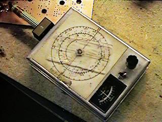
Here is a picture of one of my oroginal prototypes. This one has travelled around the world and has seen many happy radio sites in the Middle East. The switch inserts a sub-audio tone for opening tone- squelch operated communications equipment at 10.7 MHz and also injects a 1KHz tone so that I could always get a -10dBm signal to line out for setting up radio systems. This way I avoided the need for signal generators and other bulky equipment on site whilst I was working.
Several methods; Use a frequency counter, or general coverage receiver or scanning receiver. With a 144MHz receiver you can also find some of the harmonics (eg 72MHz, 48MHz, 36MHz, 28.8 and 24MHz). A Ham-band RX can be used to locate HF frequencies and HF harmonics.
When space is limited you can take a length of thin enamelled wire and solder the two ends together. Form two loops in the wire and couple one loop to the GDO coil. The other loop may be placed close to the inaccessible tuned circuit. It can for example, be placed round a thin plastic knitting needle or trimming tool.
If (for example), you wanted a bit of CO-AXIAL cable 1/2 wave long for 145MHz, then cut the cable to "Velocity factor x 150/freq" +5%. Strip and short-circuit both ends of the cable, and form one end into a loop about 1/4" Dia. Apply the GDO coil to the loop and check the resonant frequency. It will be a little low, so cut a bit off the other end and repeat. If the tuning scale is a bit too cramped then you can open-cct the other end and cut the CO-AXIAL cable for 72.5MHz (1/4 wave at 72.5 is a 1/2 wave at 145 MHz).
A GDO is always a good quick handy device for generating a signal when checking out receivers. I have added a "MOD IN" socket to my GDO which will give 75KHz deviation at 100 MHz from a high output dymanic mic. I also have an internal 1KHz oscillator (so that I could open a receiver squelch at 10.7 MHz and send a -10 dBmO signal to line as an aid to my job as a Service Engineer).
Stand outside the shop EXIT and tune the GDO between 80-310 KHz, every time someone leaves the shop. This triggers the "anti-theft alarm". If you are seen, RUN LIKE HELL! (NO - only kidding!!).
Dont forget to visit my messageboard if you have any questions about this or any other project. I always look forward to receiving feedback, positive or negative. You do not have to register to post messages.
Very best regards from Harry Lythall
SM0VPO (QRA = JO89WO), Märsta, Sweden.
EA/SM0VPO (QRA = IM86BS), Nerja, Spain.