
This is an interesting project that is so easy to assemble, useful and gives a good demonstration of my version of the uglybug method of construction. The project is an HF oscillator that can be used for a huge variety of things, for example:
The unit will generate a clean signal in the HF band with a power level of about 20mW. Not much, but you will be surprised how far you can get with 20mW (+23dBm) as a transmitter. For example, if 20 Watts will give you 5-9-9 +20dB at 200km distance, then this 20 milliwatt transmitter will give you a 5-7-9 report.
20 mW is also enough to give you a signal that can be detected by a diode probe, for pruning antennas, checking low power wattmeters or directional couplers. You can even build the oscillator into a cheap CB-type VSWR meter and have a single unit that can check antenna and cable VSWR.
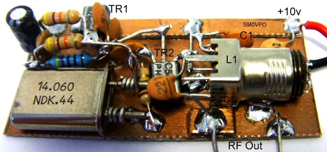
The circuit is exceedingly simple. It is a colpits oscillator and the emitter is directly coupled to the power output stage. No coupling components, no biasing components. Nothing. Only the TR2 emitter resistor limits the current drawn by TR2. Both transistors can be 2N2222, BC547, BC108, or just about any silicon NPN transistor.
L1 is a simple coil with a capacitor (6.8pf) to take it to resonance. The output tapping is 25% from the top of the coil. Since there are no other inductors anywhere in the circuit, L1 can be an air-spaced component with a 3-30pf trimmer capacitor, or a re-used IF-can and fixed capacitors. Here is a simple table of L1 and tuning capacitor values at resonance:
| Freq | L1 (air) | L1 (can) | C1 |
|---|---|---|---|
| 1.9 MHz | 60 | 25 | 150 pf |
| 3.5 MHz | 28 | 12 | 82 pf |
| 7.0 MHz | 16 | 7 | 47 pf |
| 10 MHz | 10 | 4 | 27 pf |
| 14 MHz | 7 | 3 | 22 pf |
| 18 MHz | 5 | 2.5 | 15 pf |
| 21 MHz | 4 | 2 | 12 pf |
| 28 MHz | 3 | 1.5 | 8.2 pf |
With an air-spaced coil there is more range for frequency, but for a re-wound IF can it becomes quite difficult to wind 1/2 turns. In the prototype I photographed I experimented with picking out the second harmonic but the resultrs were not so good.
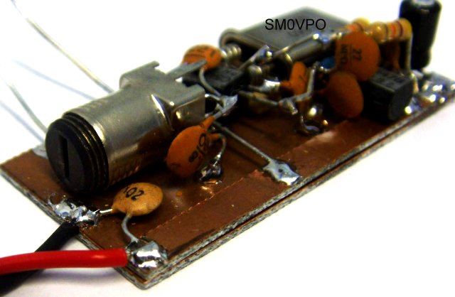
For me this is the most interesting point. When I built this project I had no PCB etching facilities at all, so I had to consider other methods. When I build such a project I always start by taking a credit-card sized bit of copper-clad board, then super-glue a strip of copper to one side and fit one large electrolytic at one end and a ceramic capacitor at the other. This gives good mechanical stability.
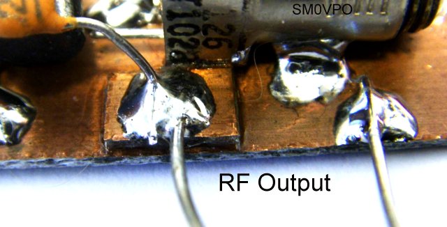
If you need to split the supply for additional decoupling (adding a resistors) then use a scalpel to cut the track and bridge it with the resistor. If you need to have lands for connecting wires, for example the RF output terminal post, then superglue another bit of coper-clad board to the base board. Like this:
If you want to make a CW transmitter of this project then change the capacitor at the emitter of TR2 to 2.2uf and key the emitter resistor. Just connect the resistor to another post that you key will short to chassis.
I have been quite inactive for a couple of years, mainly due to ill health, a demanding house and an ageing body, then selling the house and moving to Spain. I felt that my hobby had been stolen from me. This project was, in effect, a bit of thereapy for me. The project was built for a friend.
As regards the project itself, I was quite surprised how clean it was. RF output was a reliable 25mW at all frequencies, Spurious output better than -60 dBc. I even tried powering it from 19vDC (a computer PSU). Although TR2 got a bit warm, there was a good 100mW at the output pad.
If you can think of a good use for this HF marker/generator project then please do drop me a line.
Don't forget to use a filter if you use it as a tramsmitter - standard practice.
Also dont forget to visit my messageboard if you have any questions about this or any other project. I always look forward to receiving feedback, positive or negative. You do not have to register to post messages.
Very best regards from Harry Lythall
SM0VPO (QRA = JO89WO), Märsta, Sweden.
EA/SM0VPO (QRA = IM86BS), Nerja, Spain.