
Hello again, I have been somewhat active this year with sickness, making videos, and also doing much more work on my radio controlled boat. I have found several interesting techniques for different types of radio control equipment, so I shall document them in this article. The items I will discuss today are in fact several related projects and information, which will include:
| Chapter (click to go direct) | Title/project |
|---|---|
| 1 - Servo tester | One to eight channels - using Arduino (2CH in the example) |
| 2 - Extending discrete (27MHz) | Early 2CH (27MHz) RC transmitters using discrete components encoder |
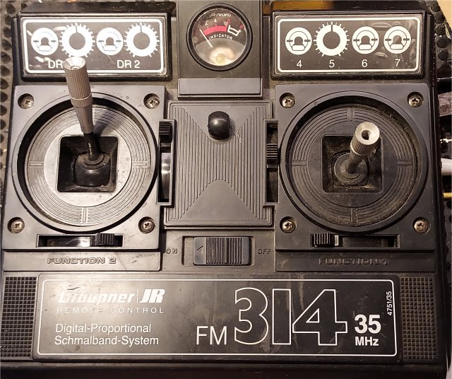
| 3 - Extending analogue (eg. NE5044N) | Analogue 4CH RC transmitters using the NE5044N to 7 channels, eg. Graupner/JR FM314 (35MHz) |
| 4 - Extending new FlySky | FlySky F8-I4X 2.4GHz from 4CH to 10 channels |
| 5 - RC 8CH decoder | Analogue decoder for 8 channels - constructional project with PCB (and receiver notes) |
| 6 - Safety & Legal | Safety and legal considerations (plus a bit of common sense) |
If you are interested in building your own RC system, extending your existing equipment or building a servo tester then this article is for you. I have colour-coded the text so you can easily scroll down to the section that may interest you, or you can click on the coloured links in the table above.
I have done some tests and measurements (for educational purposes) on the AFHDS2A with GFSK (unpublished?) Modulation system, as used in the FlySky FS-I4X and other radio control systems. I have also had much explanatory assistance kindly provided with the help of ChatGPT (OpenAI). The information I have gleaned is beyond the scope of this page, so I will create a new page for those who are interested in understanding the (probable) AFHDS2A with GFSK Modulation system (as I understand it). I have NOT used any "secret" data or documentation from FlySky - the article will be entirely from my own research. Stay tuned for this article when it is finished.
I have a load of Futaba, E-Sky, Arduino servos, and even an RC power controllers for driving DC motors. My current RC project is a 3D printed boat and I am just about ready to put it in the water. I tried it in the bathtub but the boat will only just fit in the bath, and I managed to convert my bath to a whirlpool - water everywhere. But let us first consider the servo tester.
This project is perfect to connect directly to your RC model and test all the control functions on the bench, before you add the radio. You can use it to simply check servos and RC power controllers, or even use it to remotely tune your Ham-radio antennas at the bottom of the garden. This project can be built for a single servo, or extended as much as you like, at least up to 8 channels. If you want to extend further than 8 channels (eg. 20 channels) it will work but you will have to lengthen the frame timing, and find more ports on the Arduino (this uses one port per servo). I will give you all this information after the code, as well as explaining how the code works, which is NOT normal practice with Arduino projects - Arduino authors traditionally give the end code without any explanation.
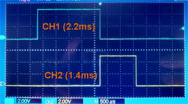
This project generates pulses of a variable length that can be fed directly into an RC servo. It will cover a wide variety of servos, and these are listed in the code, so you could have an output for several different servos that have different properties. This project basically generates pulses that vary from about 0.5ms to 2.5ms, but that is adjustable so that you can customise different outputs for different servos. In this example only two channels: one Arduino port for each servo (D10 and D11).
To build the project you only need to create a new "sketch" in your the Arduino IDE program, copy the code into it, then compile and burn it burn it to your Arduino. I use exclusively the Arduino Nano, including those cheap $2.50 Nano copies you can buy from China through Temu.com and other on-line services. They all work, but I will give a couple of tips for recalcitrant Chinese boards that did not work first time for me.
Ok, here is the sketch for you to paste into your Arduino IDE program, but only 2 channels shown. The comments tell you how to define other data output ports and use them with potentiometers:
-------------------------------- Start of sketch --------------------------------

// Analogue Proportional Radio Control of models - Servo tester
// Generates a pulse from 0.5ms to 2.5ms to test 2 RC servos (see comments)
// or use it as a standalone driver for one servo eg., remote antenna tuner
// Harry Lythall - SM0VPO - https://sm0vpo.com for more information

// SERVO DATA COMMENTS
 // E-sky servos use 800μs to 2200μs (645, 2045)
 // Sanwa servos use 830μs to 2400μs (675, 2245)
 // Futaba servos use 495μs to 1850μs (340, 1695) (year: 1975)
 // Dynam servos use 735μs to 2355 (575, 2195)
 // Luxor (SG90)  servos use 650μs to 2400μs (495, 2245)
 // (NOTE: Luxor SG90 servers rotate 360° continuously if max/min values exceeded)

// INPUT PINS
 // A0 = Servo #1 potentiometer input (0 - 5V)
 // A1 = Servo #2 potentiometer input (0 - 5V)

// OUTPUT PINS
 // D9 = Oscilloscope sync pulse (100us) for testing
 // D10 = Pulse length 0.5ms to 2.5ms for servo #1
 // D11 = Pulse length 0.5ms to 2.5ms for servo #2

// Declare integer variables used
  int timerCalculation = 0;
  int timerMilliseconds = 0;
  int timerMicroseconds = 0;

void setup() {
  pinMode(9, OUTPUT);  // Initialize digital pin 9 as output - oscilloscope sync
  pinMode(10, OUTPUT); // Initialize digital pin 10 as output - Servo #1 output
  pinMode(11, OUTPUT); // Initialize digital pin 11 as output - Servo #2 output
  Serial.begin(9600);  // Initialize serial communication (for debugging)
}

// Repeat the "pinMode" line for all the servo channels you want, but use D11, D12, D13, etc for channel 2 onwards

// GENERATE SYNC PULSE FOR TRIGERING OSCILLOSCOPE
void loop() {
  // Start of frame, read joysticks and generate channel pulses
  // Loop back continuously to repeat control frame
    digitalWrite(9, HIGH);   // Generate sync pulse for oscilloscope
    delayMicroseconds(100);   // Sync pulse duration in μs
    digitalWrite(9, LOW);    // End sync pulse
    timerCalculation = 24680; // (25000μs minus processing time outside timing loops)
	//the above values are for 25ms frames. Change 24680 to 34680 for 10 channels

// GENERATE PULSE FOR SERVO #1 ON D10
  // Read joystick, map (scale) values and send to timer
    digitalWrite(10, HIGH);    // Generate servo pulse
    int joystickValue1 = analogRead(A0); // Read joystick value
    int pulseWidth1 = map(joystickValue1, 0, 1023, 495, 2245); // Map joystick value to pulse width (650μs to 2400μs)
    delayMicroseconds(pulseWidth1); // Time delay based on joystick1 value
    digitalWrite(10, LOW); // Generate servo pulse

// Repeat the above for every test channel you want to have, using D11, D12, D13, etc.

// GENERATE PULSE FOR SERVO #2 ON D11
  // Read joystick, map (scale) values and send to timer
    digitalWrite(11, HIGH);    // Generate servo pulse
    int joystickValue2 = analogRead(A1); // Read joystick value
    int pulseWidth2 = map(joystickValue2, 0, 1023, 495, 2245); // Map joystick value to pulse width (650μs to 2400μs)
    delayMicroseconds(pulseWidth2); // Time delay based on joystick 2 value
    digitalWrite(11, LOW); // Generate servo pulse

// CALCULATE THE TIME REMAINING TO END OF 25ms FRAME
  // Calculate remaining time to end-of-frame (milliseconds and microseconds)
    (timerCalculation) = (timerCalculation) - (pulseWidth1) - (pulseWidth2); // Subtract channel pulse from frame length counter
    (timerMilliseconds) = (timerCalculation / 1000); // 25000μs is too big for delay, convert to ms (integer)
    (timerMicroseconds) = (timerMilliseconds * 1000); // How much was lost generating the ms integer (in μs)?

  // Wait the milliseconds and then the microseconds increment
    delay(timerMilliseconds); //Wait the whole milliseconds count

  // Wait μs increments lost in integer - frame now 25ms long
    delayMicroseconds(timerCalculation - timerMicroseconds);
 }

-------------------------------- End of sketch --------------------------------
As you can see, the sketch is ridiculously simple, but please note that the code doesn’t use the Servo.h library - the PCM and timing is all done in the script. Instead of using nested loops for all channels, I repeated the code for each channel. This allows you to have different timing data for different servos. It also makes it easier for my 74-year old brain. Arduino port D9 is used to trigger my oscilloscope, I use channel two to trigger my oscilloscope. This makes it easy to see channel pulses on the oscilloscope channel one clearly without it becoming unstable due to variable channel pulse lengths.
If you are buying Arduino Nano's from China, then they may have an old version of the USB to SERIAL (USB-COM) chip. The current version (written on the chip) fitted to "genuine" Arduinos is CM340G. My Nano's supplied from China had CM340C, which caused the Arduino IDE to fail to program.
SOLUTION-1 Update your Arduino IDE to v2.3.6 (or later) from the Arduino (free) download site. This revision is backwards compatible with earlier USB-COM chips and also the latest versions of the CHG340x COM-USB chip.
SOLUTION-2: Download and install the CH341SER_EXE driver then try again.
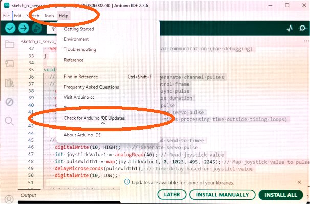
To upgrade your IDE software in your Arduino IDE window, click "Help", then select "Check for Arduino IDE Updates" and install the updated IDE package. It is all free and the IDE remembers all your previous projects and settings.
If your Arduino USB-COM chip is burnt (yes, I have burned one), then you can Google for a fix. You basically take a good Arduino with a working USB-COM chip, and then connect the serial data to the Nano with the defective CM240x. Your IDE will then program both your Nano's simultaneously, using the good Arduino's USB-COM chip.

Connect the lower Arduino to your computer and both Arduinos will be programmed with the same sketch, simultaneously, using the "good" Arduino's USB-COM module. The lower (good) Arduino can then be re-programmed for another application. Arduino Uno shown, but it is the same for the Nano.
Really ancient RC transmitters did not use channel encoder chips, but instead used an analogue encoder using proper, genuine, discrete components (remember those?). They had a master timer multivibrator to set the frame length of 20ms or 25ms, and also trigger a monostable for channel #1 control pulse. The output of channel #1 triggered the channel #2 monostable. You can add more channels by taking the output of your last channel (eg. CH #2) and feeding it into a simple monostable using a potentiometer to generate a third channel.
You can cascade as many channels as you like, subject to about 6 channels. You can add even more channels (20, if you felt so inclined) by changing the frame-start multivibrator to extend the duration of each frame to accommodate all channels. Your frame length should be at least 6ms plus 2.5ms for every channel you have. Note that each channel monostable has an RC circuit and a diode to feed the pulses from every channel to a common line. Complicated? Not at all - I understand it, and I am 74 years old! But here is a picture to show you an extended RC encoder output waveform (point P on the above circuits).

These RC transmitters came into effect around the 1980's and were used on many RC transmitters. The NE5044N can encode up to 7 channels. Many of these were used on 35MHz, 40Mhz and 72MHz RC bands. The only difference was the transmitter used a different frequency, but the NE5044N was used in both AM and FM transmitters and on all bands. These transmitters had 2, 3 or 4 channels for the beginners market, but the circuit boards were nearly all designed to encode up to a maximum of 7 channels, with a 3-pin header on the PCB for each channel.
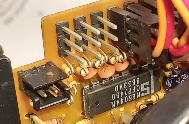
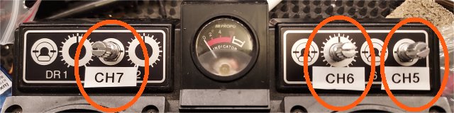
All you need to do is to add a 25KΩ potentiometer for the additional channels you want, in this case there is nothing plugged into them. The centre pin is the potentiometer wiper. The value of the potentiometer can be anything from 5KΩ to 100KΩ, but you need to use miniature potentiometers so that you have enough space on the transmitter box to mount the new potentiometers. If you look at the datasheet of the NE5044N you will see that all the potentiometer does is to vary the DC voltage from 0V DC to the supply voltage from the internal regulator (3.3V from pin 15).
Your additional channels will program the chip for the FULL range of the servo arm movement. If you want to restrict this then you can add series resistors in the positive and/or negative connections to the potentiometer. Most servos will normally give almost 180° of rotation, but RC transmitters are restricted to a pulse length range that limits them to about 90° to 110°.
Incidentally, according to the NE5044N datasheet, the NE5044N has a feature (supposedly) to stop encoding subsequent channels when a channel input is grounded, but most manufacturers did not use this feature. One other small comment is that some manufacturers erased the chip identification so you could not read any text. All you need to do is remove any links that disable the unused channels on the PCB, then count the pulses on your oscilloscope connected to pin 11. 2 pulses = 1 channel, 5-pulses = 4 channels, and so on. If you see 8 pulses then the chip is already programmed for the full 7 channels.
If you want to build stuff yourself, then the NE5044N IC still available on eBay and AliExpress, but beware of fakes. I once bought 1000 pieces LM7805 voltage regulators from Aliexpress for $20.00, and every single one of them did not function. Measurements showed them to be a non-linear resistance. They would get warm, but they didn't regulate anything. I should have known that $0.02 each was too good to be true. You get what you pay for, so "let the buyer beware".
These units seem to have become the new industry standard for radio control, and they use surface-mount ICs. These send a "standard" FlySky data stream of binary, which is nothing like the "traditional" Pulse length modulation used in the old Futaba standard. I will add another page (for educational purposes) to show you the digital signalling frames and how they are (probably) composed.
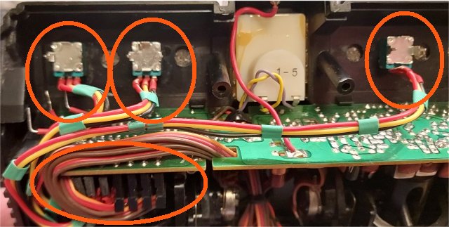
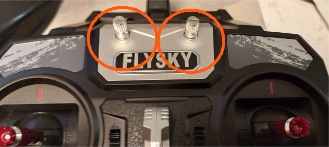
In general, manufacturers do NOT make many different boards for every combination of channels. They use a "standard" board in ALL transmitter variants, but they only add as many channel joysticks as you pay for. Of course, you can extend the number of channels, up to 10 channels, possibly more in these FlySky instruments. If you look on the board you will find joystick inputs for channels 5 to 10, but the FlySky F8-I4X only has 4 joysticks fitted, although it is supplied with a 6-channel receiver.
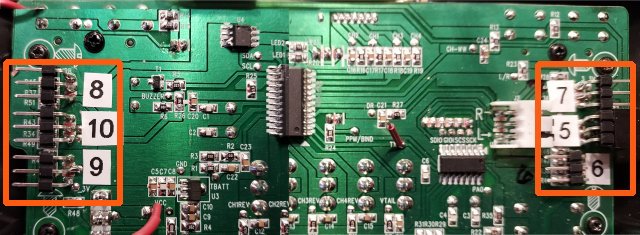
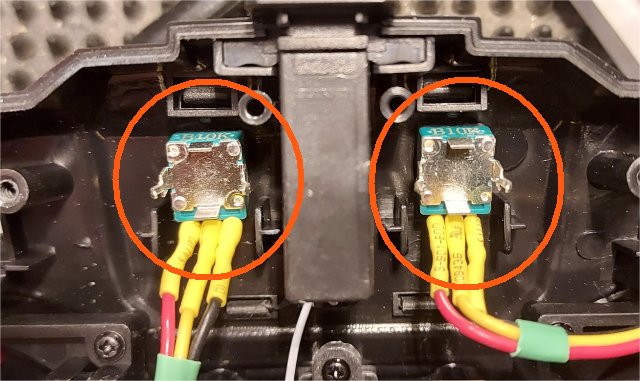
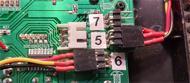
Connecting a 10KΩ potentiometer to the contacts for CH5 to CH10 works immediately. No modifications at all. As you can see I just soldered six 3-pin connectors to the back of the board, so I do not even need to remove the board from the case. To the six connectors I plugged in my six potentiometers. As you can see from the picture above, I didn't have the "special" connectors for additional joysticks, so I used six 3-pole 90° 0.1" headers on the back of the board. There are several advantages to this method, but the main one is accessibility. You can simply reverse a connector to reverse the joystick potentiometer direction, swap or add more channels, without ripping the board out of the unit and risking damage.
The board has a 3.3V regulated supply and 0V ground to all potentiometers. The centre pin of the connector is connected to the wiper of a potentiometer, which can be almost any value you like, from 5KΩ to about 100KΩ. I chose 10KΩ because it will only load the 3.3V regulator to 2mA (330μA per potentiometer) for all six additional channels. All you need do is connect a potentiometer to the channels on the board, with the wiper (middle) terminal of the potentiometer connected to the centre pin. Dead-easy!
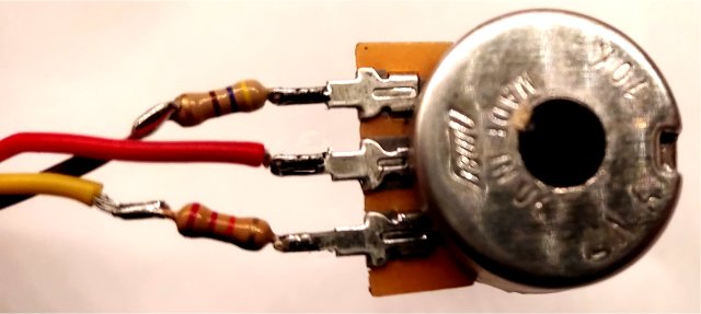
If you want all your additional channels to be identical with the joystick channels, then unplug (say) channel #1 potentiometer from the PCB and use your multi-meter to measure the resistance between the pins, with joystick and trim set to max, then repeat again with the joystick set to minimum. Select a potentiometer and fixed resistors to duplicate this. With a 10KΩ potentiometer the servos rotate a full 90°. Note that the supplied joystick potentiometer has FOUR connections. 1 and 4 are the 3.3V and 0V power. Pins 2 and 3 are connected to each of the two potentiometers on each joystick.
If you are like me and want to make your own radio gear, then I have already published an Arduino Nano encoder for up to 8 channels (see the links below). All you need do is use the data output to drive a transmitter, whether it be 27MHz, 35MHz, 40MHz, AM, FM; it makes no difference. To receive this you need a decent receiver, and the ZN414 / MK484 / TA7642 (CD7642, UTC7642, LMF501T) ICs already work for AM as a 455kHz IF sub-system. If you want FM then you can use the TDA7000 with the narrow-band modification I have given on my homepages. Again, you can use this as a 455kHz IF sub-system. But let us look at the decoder:
IC1a is a "voltage follower" so that the average DC level from the receiver decoder will be followed. The 1μf capacitor (X) will charge to the average DC level from the receiver detector. IC1a also provides a lot of open-loop gain, so that the decoder will work with very low signal levels. IC1b is a level-detector and timer. The 1N4148 diode will rapidly keep the "X" capacitor charged to almost the 6 Volt supply voltage by storing the channel pulses. If the pulses should stop (end of frame) then the DC voltage at pin 5 will fall to below 3 VDC, IC1b will change state and pin 7 will go to 6 VDC, causing the counter to reset.
Note that the capacitor marked X should be about 0.47μf. The original prototpe used old capacitors where the tolerance was something like +/- 50%. If the value of this capacitor is too large then it will work on a 2-channel decoder, where the inter-frame delay is long enough to detect and cause the counter to reset. Extending the system to 6-channels can cause the counter reset to fail due to a shorter inter-frame delay. Values as low as 0.3μf will still work.
I have laid out a printed circuit board for the new version. It is 64mm x 41mm. Maybe a little large, but you can use the decoder board and the receiver board on top of each other to form a sandwich.
All channel outputs, including Channel 9, should be fitted with 3-pin headers. Channel 9 is the 6 VDC battery connector. You CAN plug the battery into ANY of the outputs but there is the possibility of damaging the CD4017N if you put in the plug the wrong way round. Just be very careful with the polarity.
The two resistors marked "See text" are added because of a small problem with the prototype. The input to IC1a and the "voltage follower" capacitor may have a bias to always give a "high" (logic 1). This could be due to microscopic discharge of the X capacitor. The board allows you to add a small amount of DC bias to ensure the output of IC1a is always "low" (0 V) under no-signal conditions. In the prototype a 1MΩ (1-Meg) from the 6 V line was adequate, but you may get a leaky capacitor if, like me, you often choose cheaper components. You can add a 1MΩ from the 6 V line and a 1.5MΩ from the -Ve line to get a more fine adjustment.Here is the Printed Circuit Board foil pattern. The picture resolution of the board is 600 bits per inch, so if you set your print using the printer settings of 600 d.p.i then it will print the perfect size. No NOT rescale the picture or you will loose quality. I have included a 1-inch reference on the board. All the text on the copper should be the correct way round on the PCB. When you print the image to film the toner must be in contact with the photo-resist, so that the image will reverse when you expose and etch. I have reduced the size of the board in this HTML document, but if you right-click and save the image then you will get the full size picture.
Now you have an Arduino encoder on my homepages, and updated decoder (here), so you can send your RC channel pulses by any medium you like. You can record them in MP3 format and play them back, send them over a cheap mobile telephone, 315MHz or 433MHz transmitter/receiver modules, knock up a simple AM or NBFM transmitter and receiver, or even use Infra-Red or ultrasonics to get your signals to your model. If you need the datasheets for some chips, or relevant projects, then they are all here on my homepages:
ZN414 / MK484 - basis for an AM receiver (455kHz IF amplifier)
TDFA7000 modified for NBFM receiver (455kHz IF amplifier)
NE5044 7-channel RC encoder IC
Arduino 8-channel RC encoder IC
If you also have problems getting RC crystals (a common problem these days), then the 455kHz IF sub-system can be re-tuned so that you can use just about ANY TX crystal with ANY receiver crystal. Just tune the IF to the difference (frequency error) frequency. For example, if you only have a 35.180MHz transmitter crystal, then you can use a 35.160MHz receiver crystal if you tune the receiver IF to 475kHz (instead of 455kHz). You could even use a 32MHz frequency standard receiver crystal and tune the IF amplifier (MK484/TDA7000) to 3.18MHz, but you will need a couple of screened IF cans with a high-Q to get a reasonable bandwidth - increasing the IF from 455kHz to over 3MHz will result in a wider bandwidth.
I am presently working on a 16-channel decoder. I will not give out any more information here, since the old project is already described in detail on my previous decoder project and the new project is still on the workbench. Stay tuned, I’ll publish details when I’ve tested it. The only tip I will give you is that if you cannot find a ZN414, MK484, TA7642, CD7642, UTC7642 or LMF501T chip, then google for the "Sinclair Micromatic-II 2-transistor AM receiver circuit".
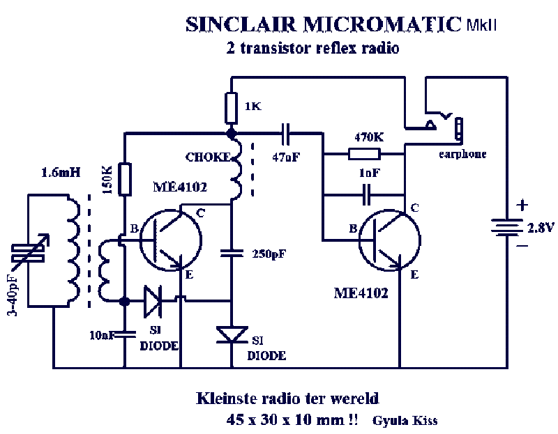
It is a sensitive AM reflex receiver, using only two transistors, and it is plenty good-enough for a short-range RC system, up to about 500 metres or more. It works well using the "Yellow" (Hi-Q) 455kHz IF transformers.
One major point you should consider is safety, or just plain-old common sense. Home-made or modified RC equipment may work well, but laws and regulations differ between countries. Some countries regulations may require "unmodified commercially manufactured" equipment. To simply add a joystick or install an approved upgrade provided by a manufacturer, may well be allowed. Frequency bands are NOT always common to all countries, and some countries may still require the RC user to hold an RC license (or pay money to someone).
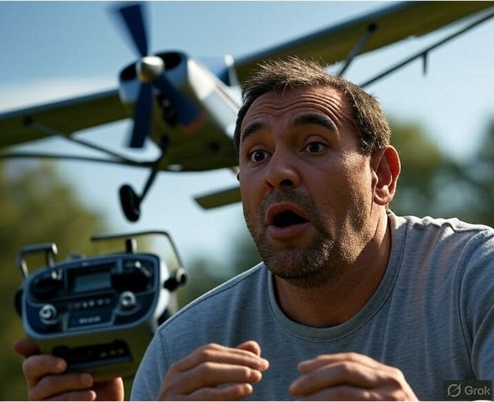
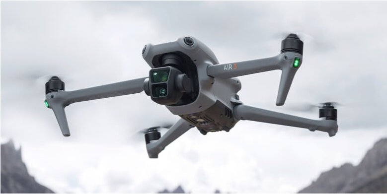
Model boats and land vehicles are short-range vehicles and do normally not pose any serious threat to the general public. Airborne models, especially those with powerful motors, and even cameras, may require the operator to undergo a training course and complete a test of competence. Here in Sweden, all airborne models classed as "drone" are to be operated by a certified pilot, unless the drone has a weight of less than 250 grammes (category "C01-toy") and/or operated at a restricted height. Drones in Sweden, even those under 250 grammes must be registered and a registration number affixed to the model.
Just one silly question for you; If I tied a heavy fishing line to my old 2kg Walkera drone and had the other end of the line in my hand, then does this become a kite? If it is "tethered" then it surely MUST be a kite, and therefore exempt from the drone laws? No! I do not think I will try proving that in reality.
In almost all countries, all radio transmitting and receiving equipment must be "so designed and constructed as to minimise the risk of interference with other radio communications services". Some of the RC bands are also shared with other services, so the risk of interference to and from other services can be a strong possibility, especially on the 27MHz, 315MHz and 433MHz radio bands, which can be used for computer wireless solutions, garage doors or car remote keys. The third harmonic of 40MHz also falls in the aircraft band. When operating, on typically 27MHz, 35MHz, 40MHz and 72MHz, a coloured flag must be attached to the transmitting antenna so other RC users can see the frequency/channel upon which you are operating. Most users today use 2.4GHz, but there are still many enthusiasts, like me, who use real radio frequencies.
In most countries, radio amateurs have to study and take examinations to prove competence in designing and constructing radio equipment. Ok, there are some countries where the license only requires you to call the king "Daddy", or have sufficient zero's in your bank account. But over 99% of radio amateurs are educated. There are spot frequencies allocated in some ham-radio VHF and UHF bands for digital and control equipment. This may be covered by the radio amateur's license, so if you are a radio-ham, then it is a good idea to check your licensing conditions.
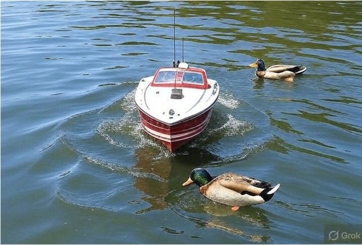
It is your responsibility to ensure that any home-made radio equipment, changes or modifications to commercial radio equipment, is allowed. Remember that the radio licensing authorities take a dim view of people being "assaulted" by a potentially dangerous model; there is nothing worse than being hit in the face by a propeller on a powerful motor, or having limbs slashed by helicopters or drone rotors. You will probably get away with chasing a duck on a pond, but physical injury to bystanders will almost certainly become a police matter. Just use a bit of common sense - regulations and restrictions are implemented or tightened to stop historical incidents (or hysterical politicians). Please do not add to the list.
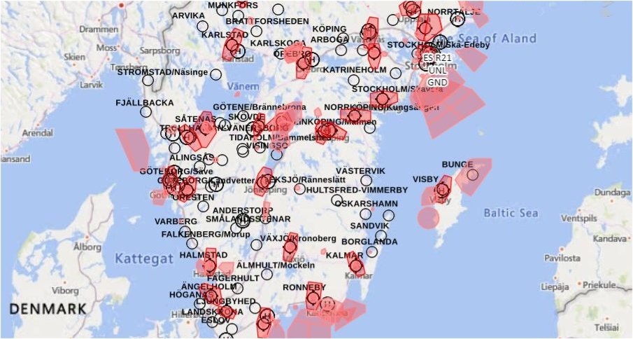
Finally, in the 1950's to about 2005 there were many boating lakes with areas designed for model boats, today most are owned by clubs. Today most clubs have jumped on the "gravy-train" (money band-waggon) and you must now pay club subscriptions to the local club before you can use them. All airports are surrounded by a "no-fly" zone, typically 5km (3 miles), and also an extension along the flight-paths in line with runways. Some airfields may allow you to fly up to 50m high within 5km to 8km (3 to 5 miles). RC drones operated near airports may normally be used indoors without restrictions, but they must still be registered. Just check your country and airport authority's local regulations before you use RC models.
In this page I have given you several ideas for radio Control of models. I have shown you how to contruct your own servo tester, with different output, even outputs tailored to different types of servo. I include extending the number of channels using three different technologies, from "Anciano" (ancient) using discrete components, later equipment using NE5044N (or similar), and then "hacking" the latest 2.5GHz RC transmitters. I apologise if I was a bit long-winded with this article, but I AM an engineer (retired), and you should NEVER expect a simple statement from engineers. If you are an engineer then you may appreciate the technical gobbledegook and assumptions I will provide about 2.4GHz systems. If you have any more information on this subject then please contact me.

Finally I mentioned safety and legal considerations - how stupid can they get?. It is a fact that in days of old, when knights were bold, and toilets were not invented (early 1900's), you could take a "charabanc" trip to Cleethorpes and let the kids rent a 1/2-ton, wooden, 2-stroke petrol-powered boat on the boating lake, until you heard the office anouncement over the speakers "Come in number 6, your time is up!". Today even older children MUST be accompanied by an adult, and everyone MUST wear a safety floatation-vest, even if the water is only 2-feet (60cm) deep. On some lakes you also have to pay a deposit to be sure that you are not going to steal the blooming 1/2-ton, water-soodden, leaky old boat! True! But all these new regulations and restrictions are prompted by real "incidents".
As a radio-controlled enthusiast I beg you to operate responsibility. It is so easy today that just a little incident can affect new rules and regulations for everyone, with even more restrictions. You will be surprised at some of the WeIrD restrictions there are in the world. A classic example is that in Brooklyn, New York, it is illegal to have a donkey in a motel bathtub. One cannot help but wonder just what someone did to cause the need for that law! (not that I have any desire to have a donkey in a motel room).
So thank you very much for paying a visit to Harry's Homebrew Homepages and for reading as far as this. I hope that this project has given you some "food for thought". You can always e-mail me at harry.lythall@[my domain].com. You can even use hotmail@sm0vpo.com (not a tipping error) or british.inteligence.sweden@sm0vpo.com (not a spellling error), as they are both valid e-mail accounts for me 😉, although I would prefer that you visit my messageboard if you have any questions about this or any other project. I always look forward to receiving feedback, whether it be positive or "constructive" 😊

PS - Pictures used in this article that I do NOT own are NOT hosted on this server; I have linked to the source(s).
Very best regards from Harry Lythall
SM0VPO (QRA = JO89wo), Märsta, Sweden.