
I am presently building a Radio Controlled (RC) boat, about 1 metre long. When I was a kid in the 1950's and 60's my parents would not allow me to have any expensive toys. Now I am 72 years old I can do what the heck I like and realise old dreams 😉. With home-made radio equipment and a 3D printer I do not need any serious money to build it, either.
This model is a "Submarine Chaser" model. I have the 3D printer running 24/7, and the total running time to date is just under 300 hours. Yes, it is a slow 3D printer, about 50-mm/second. Modern 3D printers can write at 600-mm/second, or even more. Now that I am on a pension, money is tight, so I can do other projects while the Prusa Duplicator i3 is plodding along at a snail pace.
The hull is now finished, with home-made propellor shafts, rudder and cabin. I have even added a control consol inside the cabin, with micro-panel lamps (otical fiber cable strands). Guns and lamps are steered by radio. In principle, my boat is built and finished, all I have to do is use filler, sand it, paint it and then fit all the electronics and small details. Then it will be chasing ducks on the Märsta duck-pond (should I also add a water-canon?).

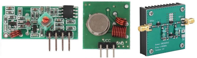
The boat uses a home-made 6-Channel Radio Controlled system, as described elsewhere on my homepages, but the transmitter and receiver are 433MHz modules that you can get from E-bay for about $10. I also bought a 3-Watt Power Amplifier module for about $7, which boosts the transmitter output power considerably. I bought modules because they are so cheap and it will save me hours on the workbench.
The servo motors were an educational bulk-packet of $20 for four micro-servos, intended for lessons on the Arduino microcontroller (I am NOT using an Arduino). The twin motors are the standard "540" type, 12-Volt, 1.5-Ampere motor with brushes (so it is reversable). The battery is robbed from an old laptop computer.
All this project gives me a small problem - I need to build a motor speed-controller that will handle 15-Volts DC at 5-Amperes. It needs to accept the "Pulse-Width-Modulation" (PWM) pulse from an analogue Radio Conntrol receiver. It must also give both forward and reverse functions. I have a heap of older servos that I last used many years ago, but now at long last, they can see "the light of day".
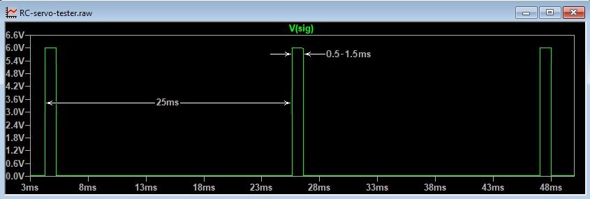
To test the servo motors and to test the motor speed controller I need to generate a single-channel RC signal that will drive one servo, exactly the same as I will receive from my RC receiver decoder. The pulse it delivers is a posivive 5-Volts pulse with a variable pulse width. The pulse width varies from 0.5-milliseconds to 1.5-milliseconds. With joystick centered at the transmitter, the pulse must be 1.0-milliseconds. After the pulse, there is 0-Volts waiting time for the channel pulse in the next frame, and that is about 20-milliseconds to 25-Milliseconds. So all six channels are repeated 40 times a second.
My first thought was to use a PIC16F624 single-cip microcontroller, but that is NOT as easy to code as I thought it would be. I then tried Chat-GPT and even Perplexity.ai to write some code for me. Both of these "intelligent" sites failed and I could see loads of errors. Chat-GPT made loads of basic mistakes, such as defining AD0 for potentiometer (joystick) input port, and RA0 for the output. They are both the same pin on the PIC16F624 microcontroller chip. Perplexity.ai wrote code, which had loads of timimg routines, but not a single output instruction. It also called the 500-millisecond configuration delay as the frame delay, and the frame and start delays used exactly the same code, with the same parameters. I gave up!
This little project is my own version of a simple multivibrator. It uses a 10KΩ linear potentiometer to vary the pulse width. It also has a fixed 25-millisecond delay that simulates the delay from the analogue RC receiver. It uses only two BC547B transistors, but I have added switching diodes as a modification to make the square-waves more square. A simple multivibrator has an unacceptable leading slope. Since the Mark:Space ratio of the signal is 25:1 this problem only gets worse.
My unit was devised and calculated, then tested using LT-Spice. Now built on a prototype breadboard. It functions perfectly and took considerably less time than I have already spent trying to code the PIC16F624 microcontroller. Here is the result of my experimenting:
The circuit of the unit is given below and is a conventional multivibrator. Just ignore D3 and V2. V2 is a 200-microseconds pulse that hits Q1 base terminal, to initially start the multivibrator running in LT-Spice. Without this addition the oscillator will not oscillate since each half of the multivibrator, Q1 and Q2, start in a "stable" state. If anyone has used LT-spice then you will be familiar with the problem, so I have left it in for information. D3 and V2 are NOT part of the project and do not appear on the Printed Circuit Board (PCB).
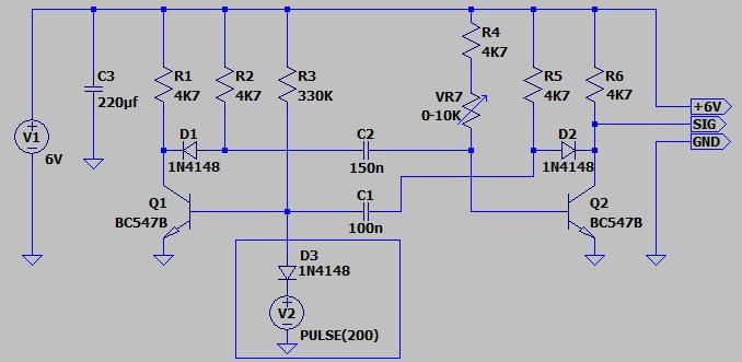
When the collector of Q1 switches to 0-Volts, then C2 (charged to 6-Volts) will push Q2 Base to a negative voltage. C2 charges through the control potentiometer, but as soon as it becomes higher than 0.7-Volts on the Base of Q2, then Q2 will conduct. When Q2 conducts, then it's Collector goes to 0-Volts, and the charged C1 will put a negative voltage on Q1 Base. Q1 Collector then goes high and lifts the voltage on Q2 Base. At least, until C1 charges through R3 and Q1 gets turned ON again. Then the cycle repeats.
R3 (330KΩ) and C1 (100nf [0.1uf]) have a time-constant of a around 25-milliseconds, the actual frame delay value is not at all critical. Q2 Collector will therefore be 0-Volts for over 24-milliseconds. R4 (4K7Ω) + VR7 (0 to 10KΩ) together will have a combined value that varies from 5KΩ to 15KΩ, so the positive pulse on Q2 Collector will vary from 0.5-milliseconds to 1.5-milliseconds. VR7 simulates the RC joystick. In the joystick center it it 5KΩ, which will give an output pulse of 1-millisecond.
D1 and D2 have exactly the same function, so let us look at D2 and Q2. When Q2 conducts it will sink the voltage on R6 and R5 (through the diode D2). When Q2 stops conducting, then the impedance at the collector of Q2 is much higher, and only the two 4K7Ω resistors are pulling the voltage up to 6-Volts. The capacitor C1 will therefore have a "rounding" effect on the positive pulse at Q2 Collector. However, with this modification, D2 becomes reverse biased and so prevents this rounding effect from happening, giving a really clean text-book square-waveform.
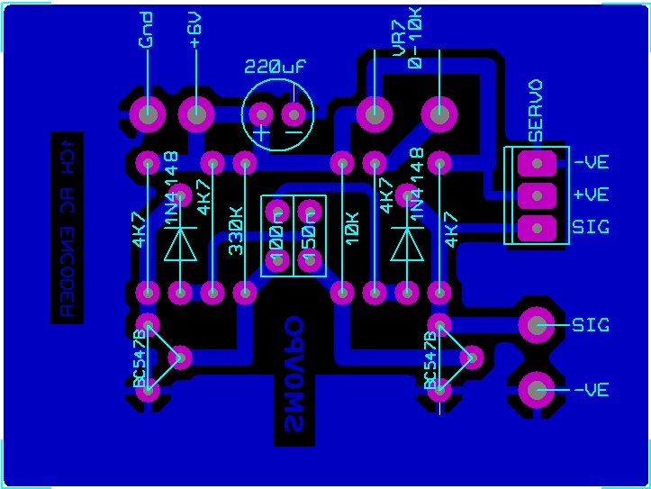
The circuit is constructed on a single-sided PCB measuring 2" x 1.5" (50-mm x 37.5-mm). All holes are 0.8-mm diameter. The 0-10KΩ potentiometer is mounted external to the circuit board. There is a pad on the PCB for a 3-pin header so that a standard Futaba-compatible servo can be simply plugged in. The servos supplied for the Arduino training use the same pin-connections and signal format. I have also added SIG and GND pads so that you can connect the output waveform to any other device, such as a computer input, or radio transmitter modulator.
The PCB foil pattern is very large so that it will not be "pixely" when printed. Do NOT rescale the picture. I suggest you import it into an MS-WORD document and adjust the size of the picture using the word-processor's ruler function. You can also open the file using PhotoShop or Paint Shop Professional and change the "Printer Resolution" to something like 600 d.p.i. for the printer size. Then do a test printout and measure the size of the printout. If the test printout is, for example, 77-millimetres wide, and you used 600 d.p.i then the new printer resolution can be set to 600 x 77 ÷ 50 = 924 d.p.i. Or as a percentage 100 ÷ 77 x 50 = 65%.
Here is the PCB foil-pattern. Right-click and select "Save image as ..." (rc-servo-tester-1.pcb100.gif) to save the picture full size. I have reduced it visually on the screen so that it will fit on the page, but this does NOT affect the image resolution.
If you are wondering why every component connection to ground is a pad with a couple of tracks to the ground-copper, this is so that the surrounding copper ground does not suck heat away from the pad. It is called a "Thermal-Break". It also prevents solder from spreading off the pad to the ground-copper and making the project look messy.
This project is a simple way of generating a Pulse-Width-Modulated signal for driving RC servos and other RC equipment. It was developed and tested during two sleepless nights. You can use it for a number of applications, for example:
I hope that this project has given you some "food for thought". You can always e-mail me at harry.lythall@[my domain].com. You can even use oeieio@hotmail.com or hotmail@sm0vpo.com as they are both valid e-mail accounts for me 😉, although I would prefer that you visit my messageboard if you have any questions about this or any other project. I always look forward to receiving feedback, whether it be positive or negative ☺
Very best regards from Harry Lythall
SM0VPO (QRA = JO89WO), Märsta, Sweden.