
In days of old, when knights were bold, and toilets we not invented ... Deja vous! Yes, I am back on the PCB tuning capacitors, but this time I have built a VHF/UHF oscillator to illustrate the technique. I will add the PCB foil in the download section, but the priority is low. The object of this article is to show you my experiment to demonstrate a technique.
The previous tuning capacitor article is intended to meet the higher capacitance requirements needed for MF and HF uses. The capacitor is also intended to have some form of routine adjustment device, such as a knob. But this project capacitor is intended to be set only on occasions - a preset tuning capacitor.
The tuning capacitor stator vanes are etched on to the oscillator PCB, and the rotor vanes are etched on to a seperate board, which is clipped out and bolted to the oscillator board.
This capacitor is of the "butterfly" type that tended to be expensive and are today quite rare. There are two stator vanes that are physically mounted on the same plane. This gives them almost no starting capacitance at all. The rotor is the butterfly-wings, which when placed over the stator vanes, creates two capacitors, in series.
This technique gives a much wider capacitance range than a standard tuning capacitor, as well as a much lower minumum capacitance. This is ideal for VHF and UHF work. A standard air-spaced tuning capacitor has a typical capacitance ratio of 10:1, resulting in a tuned circuit frequency ratio of 3:1. This is the reason the old MW band was 550kHz to 1.65MHz (the "standard IF of 500kHz was chosen because that was the international maritime distress frequency at the time).
The butterfly capacitor can have a much higher max/min ratio: typically 16:1. We need this at VHF because the low residual wiring capacitance become significant as the tuned-circuit increases in frequency.
If 0.5mm thickness fibre-glass board is put between copper plates, then I get about 6pf per square-centimetre. The area of my two butterfly-vanes are each 1.4cm, so I have about 8pf + 8pf. I could have grounded the rotor and had a 16pf variable, but I chose to use them in series to get a 0 - 4pf variable capacitor.
I used just one bit of board and photo-etched both the main circuit and the rotor vanes all in the same etch. Those sort of "ringy-thingies" above the rotor are NOT my idea of a self-portrait! These are to be drilled with a 3mm bit and cut out to make insulating washers. You need only one of them, if your bolt head comes anywhere near the stator vanes on the board. I used 0.5mm thickness PCB, so you can almost cut out the rotor with a pair of stout scissors. Drill the centre of both caps with a 3mm bit, and secure the rotor to the board using an M3 nut and bolt ("Screw and nut" if you work for Ericsson).
 |
The text on the PCB must be the correct way round when the copper is viewed (above). The pattern of the PCB file is backwards (viewed from the component side of the board). I draw it this way so when you print it on to film the ink/toner will have to be in direct contact with the photo-sensitive lacquer. Make sure the pointer is positioned as shown in the component overlay drawing, with the copper-side down. The pointer/rotor is fitted to the component side of the circuit board.
 |
The components shown in red are fitted to the copper side of the board. The area coloured yellow and blue is the pointer/rotor vanes of the capacitor. The pointy bit of the pointer/rotor is for you to adjust the capacitor, and change the frequency of the oscillator. You can mark the PCB with the frequency information using a felt-tipped pen. The fibre-glass keeps your finger away from the capacitor so it is not at all "touchy" to adjust. Adjust it with the point of a screwdriver, anyway.
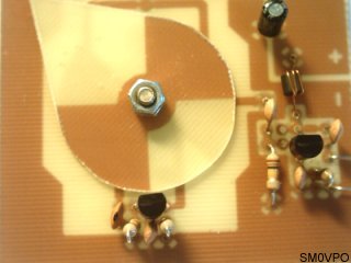
The top view of the capacitor shows clearly the two locknuts. They are tightened so the pointer binds a little, does not shake, but is easy to move with very little pressure. You can also see the other components with the oscillator in the foreground, and the buffer stage to the right. If you compare this with the component overlay then you may notice something "fishy". Tests your powers of observation. If you did not then see Tut Tut! at the end of this article.
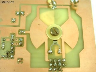
The bottom view of the board shows the tuning capacitor, and the nice thing about playing with 0.5mm board is that other layers can be seen through the board, especially with a little help from PhotoShop.
By the way, the amplifier/buffer stage does NOT have the transistor holes in the correct position for the device. TR2 is to be rotated and the legs "splayed out" so they fit in the correct holes. You could alternatively fit a bipolar 2N2369, change the 100K to 22K, and add a 47K in the two vacant holes. But 2N2369 seems to be a rude word with some constructors, especially in Europe and the Middle East (See! I do read my massage board :-).
The bearer circuit for this capacitor is a simple FET Hartley oscillator, TR1, as used in my GDO project. The inductor for the oscillator is also fabricated on the PCB, so all the frequency determining components are all done for you. The circuit is quite straightforward so I will not go into any great depth of explanation; I am a real lazy bugger, today!
This circuit is actually a prototype oscillator for my TV transmitter, but the circuit, as it stands, can only generate a simple un-modulated carrier wave, with an output level of about 5mW, in the 200MHz to 350MHz ranges. See Frequencies below.
The maximum frequency of this circuit is about 450MHz, but if you change the BF245 to BF959 then you should be able to get up to 600MHz, with suitable PCB changes, of course. The changes involve scaling the capacitor and inductor.
On the back of the board are three components. They have to be fitted here so they do not obstruct the pointer. The 103 cap (10nf) is supply decoupling, the 47R is the supply feed to the oscillator, but the grey 10pf is part of the frequency determining circuit.
The basic board frequency range is 285MHz to 350MHz, which is quite good for a VHF oscillator. It is also surprisingly stable, has no microphony, and is a good building- block for other projects that do not require crystal-controlled stability, ie, WBFM and TV.
For 285MHz to 350MHz the grey 10pf is not fitted. That capacitor lowers the maximum frequency to 225MHz, which is in the upper portion of the TV VHF Band III. With the grey 10pf fitted the unit has a frequency range of 190MHz to 225MHz, which covers the TV channels in the table below. You can change the grey cap to 12pf to cover a little lower.
| USA | Europe | China | |||
|---|---|---|---|---|---|
| Freq (MHz) | ch | Freq (MHz) | ch | Freq (MHz) | ch |
| 187.25MHz | 09 | 189.25MHz | 07 | 184.25MHz | 08 |
| 193.25MHz | 10 | 196.25MHz | 08 | 192.25MHz | 09 |
| 199.25MHz | 11 | 203.25MHz | 09 | 200.25MHz | 10 |
| 205.25MHz | 12 | 210.25MHz | 10 | 208.25MHz | 11 |
| 211.25MHz | 13 | 217.25MHz | 11 | 216.25MHz | 12 |
France is excluded from the table. They have their own system. They basically copied the UK system, but changed certain key items to prevent Brits from watching their "Rue De La Sesame".
If you are in the UK then you may not have access to channels below channel 21 (471.25MHz), mailnly because loads of people have spent the past 30 years making loads of cash selling the lower frequencies to business and commerce, while the rest of the world were watching "Muffin The Mule". on 170MHz. Ok, so we did have 50MHz, 405-line TV, but that was given back to the radio amateurs, and about time, too!
If you intend to build this project, then the component overlay is correct, NOT the photographs. But first let me tell you a little story:
In the USA, many years ago, a film was made in which the film producer wanted a very special sunset, with cliffs, and a romantic couple. They toured the whole West coast of the USA, but were unable to find a suitable location. So they went to the East coast, found a nice site and filmed the sunrise. This sunrise was projected behind the romantic couple, and the film was played backwards. Great. Instant sunset!
Throughout the whole film clipping, editing and reviewing, no-one had noticed that the waves on the sea were leaving the shore, instead of coming in to shore. It was noticed at the first public performance.
The point is that when I made the PCB I accidentally got the artwork the wrong way round. So I built it backwards, then used PhotoShop to flip the pictures horizontally :-) The only problem is that the BF245 transistor Gate was at the wrong end, so I reversed it. In the photograph it appears to be the wrong way round, but I had hoped it was too blurred for you to see ;-)
As long as space is not a problem, then you can make both inductors and capacitors on PCBs. Here in Sweden, it costs me typically US$10 for just one capacitor. The cheapest one at the moment is US$3, and the second cheapest is US$9, including purchase tax. This is why I have not fitted one to the V5 FM wireless microphone. But now I am compelled to have something for the coming TV transmitter project, since I cannot have 6 transmitters all on the same frequency. Now I have a suitable alternative, and at the right price for me.
If you are involved with component manufacture, or component supply, then please bear in mind that the consumer has a limited number of zeros available, and fantasy prices are stoopid! In 1990, whilst working in the Middle East, I used to buy preset variable capacitors from China at 10 pieces for US$1. In 15 years they have become 100 times more expensive = 10000% inflation. A new car has only gone up 3x, a "Mars-bar" and "Bounty-bar" has only gone up 2x, but my salary has only increased by 1.6x. Now that should say something to you.
Very best regards from Harry Lythall, SM0VPO, Sweden.
(But if you are an overpriced component retailer, then I hope your balls turn square, and fester into corners.
Dont forget to visit my messageboard if you have any questions about this or any other project. I always look forward to receiving feedback, positive or negative. You do not have to register to post messages.
Very best regards from Harry Lythall
SM0VPO (QRA = JO89WO), Märsta, Sweden.
EA/SM0VPO (QRA = IM86BS), Nerja, Spain.