
The design shown will test PNP and NPN transistors, diodes and SCRs both "in-situ" (equipment of course de-energised) and also by direct connection to a stand-alone component. It is a simple GO/NOGO test which can identify diode and transistor action and will indicate diode polarity and transistor type PNP/NPN, if this is unknown.
The CD4093 CMOS IC (IC1a & b) is configured as a square-wave oscillator of about 2Hz. IC1 c & d invert this 2Hz signal. These two complementary square wave voltages are used as the test supply voltage to the Device Under Test (D.U.T.). Transistor base bias is via a 1000-Ohm resistor. Two red LEDs are paralleled in Ĺcontraĺ fashion and connected across the output. Current flow through either led is limited by the 470 Ohm resistor and either LEDĺs P.I.V. is clamped to about 1.7v, which is the ON-state voltage of the other LED (being in the conducting state). With no D.U.T. connected to the tester, and TEST push button pressed, both LEDs will flash alternately.
If a healthy transistor is now connected: during the half-cycle during which it will be biased ON and therefore heavily conducting, one LED will be effectively short-circuited and remain dark. On the alternate half-cycle, the polarity of the applied signal will not cause the D.U.T. To switch ON and current can then flow through one led causing it to illuminate. This appears as a 2Hz flashing of the LED.
It should therefore be evident that if the D.U.T. is:
The purpose of the two strings of series connected silicon diodes, connected in series with the D.U.T. may require some explanation:
Their function is to allow only a current pathway through the D.U.T. provided that it is in fact fully saturated (turned hard-ON) and that insufficient current could flow through parallel circuit resistances such that one or both of the LEDs would be dark due to this.
Remember this design is called an "in-circuit" tester (no messy de-soldering, to isolate a suspect faulty semiconductor!).
In order to test SCRs and diodes, S1 is thrown to the appropriate position, in which one of each of the two series connected pair of diodes is switched out. This is necessary because: the forward ON-state voltage of a healthy diode or SCR being about 0.7 volt, then three conducting series junctions would present about 2.1 Volt across the LED, which should normally be dark.
Therefore the LED would not extinguish as it should and therefore give an erroneous test. The Gate voltage for the SCR is via a 100-Ohm resistor.
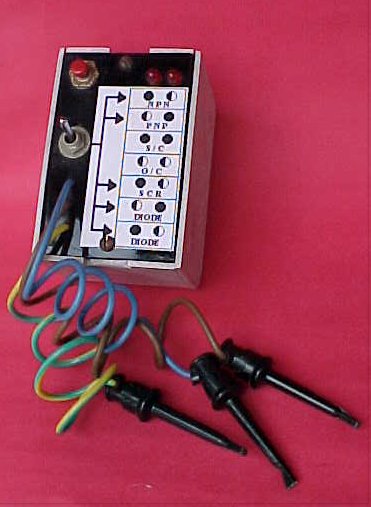
Suffice to say that I have constructed this design and it has provided good results with both small signal and power type transistors, SCRs and diodes of various ratings. From the picture shown and the schematic, a simple front panel graphic is provided this indicates what all the flashing and unlit LEDs actually mean! I have used E-Z type hooks to connect the device to be tested. Supply is a 9v miniature battery.
Note: this is my "CMOSĺed" adaptation of a similar design appearing in the English magazine "Television" in June 1983. I present it here for the benefit of all electronics enthusiastĺs still working with discrete semiconductors!
All the best till next time. Cheers & 73's
FRANK V HUGHES
PS - The little visitors cct has a few typo's viz:
If you have any questions related to this project then please refer them to the author Frank V. Hughes.