
Contrary to what some radio experimenters think, a bipolar regenerative design can be made to work efficiently. The major concern is the low input impedance of the detector-amplifier bipolar stage. Nevertheless, it can be easily compensated with positive feedback or regeneration. A sufficient amount of regeneration can make tuning astonishingly sharp.
Another concern is the quality of the detected audio. This, to my knowledge, is subjective. The quality of sound coming out from an earphone can be rated good or fair by two different people. I would suggest that you decide by yourself. So, come on and try the following schematic for the 530 kHz to 1650 kHz AM Broadcasting Band.
Please notice that the 475 pF variable capacitor tunes in the stations whereas the 200 pF variable capacitor controls regeneration. The latter is known as the throttle capacitor. L2 is the tickler coil. In order to regeneration to take place, L1 and L2 must be correctly phased ( very important! ).
The power consumption is very low. The 2N3904 drains some 60 uA from the 9 volt battery and the AC126, about 0.5 mA. As a benchmark, medium powered ( 5 to 10 kw ) local stations within 25 km from my site are heard as fair to loud audio signals. Here are two views of the prototype:
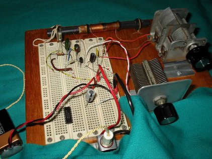
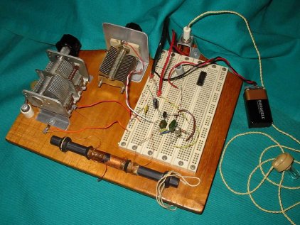
I can happily give details on the coils to people interested under request ( I use a black plastic 35 mm film container and #20 AWG enamelled wire ). Finally, I'm using a solderless breadboard for the connections between components ( a practice not recommended for RF by purists, but it worked in my case ).
| Ramon Vargas If you would like to know a little more about the author, he is 49 years old, married and has a son. His son is not interested in Electrnics. Harry |
 |
If you have any questions related to this project then please refer them to the author Ramon Vargas.