
The author of this project wishes to remain anonymous since the project could be used for pirate radio as well as amateur radio applications. The circuit was intended for use with a wide-band FM link transmitter, presumably to hide the program content provider from discovery, in the event the remote radio transmitter was discovered by the authorities. In amateur radio, the circuit could be used as a receiver for the 50MHz band directly, but for other bands with suitable modifications, such as the 35MHz FM radio control band, 29.6MHz FM. The description provided by the author is:
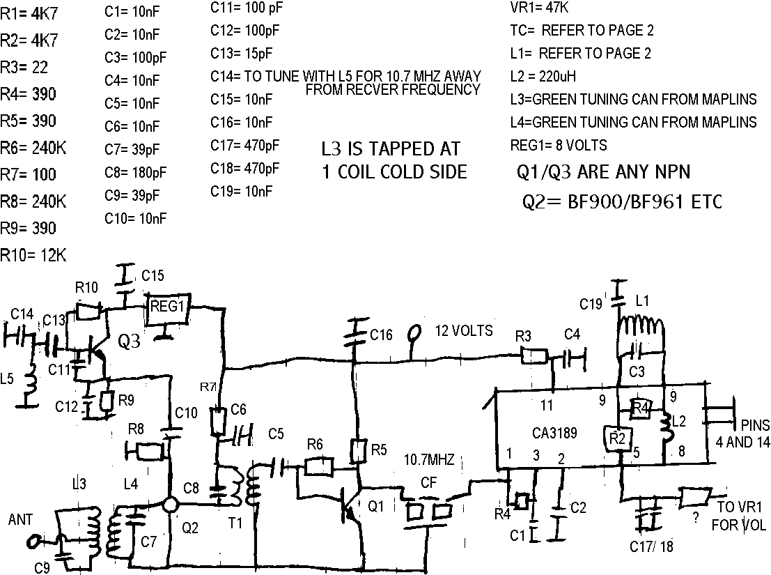
The circuit is for a Band-I (48-74MHz) receiver. It took me over a year to get my hands on it and now I want to get it up on the web so others can make it and to help the people who are trying to get started in radio, whether they are pirate or amateur. The circuit is hand drawn. T1 is 10 turns on the dual gate side and 3 turns on the other. L1 is 20 turns on a 5mm diameter tuning can like an IF can with a 100pf cap on the outside. If you ever decide to make this kit please let me know, I will buy a few. I have made one and it works great. I think that it would make a good circuit for your page. I hope you make one and design a PCB for it as I build it but sticking bits of copper board on a sheet of copper board, but I would like to make it properly. I have seen the other version that Veronica makes. They just have a meter and auto switch on them. But they cost £170 for about £15 worth of parts. Cheers - Anon.
I think the design is basic but clever and I may well take the authors suggestion to make a PCB for the project. But that is a job for the future.