
I have already made several Audio Frequency generators, but to be honest it is not worth much effort for me to make one. I have used an EPROM AF Generator with a sinusoidal data-table and a resistive D/A converter. More recently I built a retro Wein-Bridge audio generator using a thermister for control. But today you can download an AF generator application for you mobile telephone, even an audio spectrum analyser.
If you do not want to muck about or risk your $650 mobile telephone on the workbench, and you already have an RF generator with Amplitude Modulation (AM), then you also have an AF generator handy. I am lucky to have a £6000 RF generator. It can deliver up to 1-Watt of RF. Internal modulation ranges from 0.1 Hz to 250 kHz. I can use this as an "all-singing, all-dancing" audio genrator using only 5 components on a small board. If you accidentally stuff a few volts of DC into it then you will not damage anything, at least nothing expensive. Maybe just a diode.
If your RF signal has amplitude modulation, then all you need do is to use a simple diode detector to recover the audio. Then you have got an audio source. If you have no AF generator and need one now, then you can cobble one together within just five minutes. All you need is two resistors, one germanium diode, one electrolytic capacitor and one small ceramic capacitor. The 47pf capacitor can also be missed if you use a coaxial cable from the board to the project.
This will probably be the simplest, easiest and most useful project you have ever built. It uses no transistors, Integrated Circuits, or any active device. It needs absolutely no power supply to run it.
The circuit diagram is really easy. It is basically an un-tuned "Crystal Radio" receiver, but it is complicated only by the addition of an electrolytic capacitor to block DC from the output terminal. This is one of those projects that are best built as a rat's nest.
Complete circuit of the RF Generator to AF Generator converter card.
I didn't bother to make a Printed Circuit Board (PCB). I didn't think that the project waranted a board. Instead I cut a bit of un-etched copper-clad PCB, about 4cm x 5cm. To this I super-glued three little PCB offcuts, about 5mm x 7mm. The actual sizes are not all critical. You can read the dimensions as inches and get a much bigger board. You could even build it in a nice posh box, but the construction method will have absolutely no effect whatsoever on the final project. Here is the finished project:
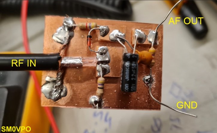
Completed RF Generator to AF Generator converter card.
Note that none of the components are critical. You can vary the values by about +/- 50% without any noticable change in performance. The 4.7KΩ resistor should really have been 10KΩ in the days of the ubiquitous "10K-Probe". The 47Ω resistor is just a load for the RF generator. My RF generator shuts down if the reflected power at the output exceeds about 100mW. The 47pf is to smooth the recovered AF from the received audio. I chose such a small value so that I can use the 500kHz modulating frequency. If you are only interested in 20Hz to 20kHz then 500pF or 1nF is ok, but I sometimes need frequencies of up to 250kHz. The 2.2μF capacitor can be as low as 100nF. I used 2.2μF because I find it useful have really low frequencies, like 1Hz, or less.
The input plug is not mounted on the board. I just cannibalised an old N-type to "something else" cable and soldered the cable directly on the project board, leaving the N-type connector on the other end of the cable. The cable can be as long or as short as you want it to be. The diode can be an old Germanium diode, but a 1N914, 1N4148 will give excellent results if the RF level from the generator is kept high. If you want really low audio levels (eg. <10mV) then use a Zero-Bias Schottky diode.
To use the RF Generator to AF Generator converter, plug the RF-input to the RF-output. Set the RF generator to the highest RF output available. Set the frequency to "somethng high". I use about 100MHz, but it can be anything from 25MHz to 1GHz. Set the modulation level to the highest you can get, not more than about 80%. Set the generator modulation source to "internal" and "sine" (if these options are available). Select the modulating frequency to the audio frequency you want.
Now you can connect an oscilloscope to the two output wires and view the audio level received from your RF signal generator. I use two crock-crock (alligator) test leads to couple the audio to my circuits on the bench, but you can still use an oscilloscope probe if you need a BNC input to the circuit that needs audio input. If you see low-level RF on the output waveform then you can increase the 47pf, or increase the generator radio frequency.
Adjust the audio level by either adjusting the RF generator modulation depth, or the RF level. Either will work, but you get much better linearity if you adjust the modulation depth. This is because the signal diode in this project has a forward bias level, which means that it needs typically 1V R.M.S. before the diode will conduct anything and still decode AM. At low RF levels it can also become non-linear. It is better to lower the modulation depth in this event.
So that is it!! Could it be more simple?
(That was a rhetorical question 😉. I once lost my company ID card and so I posted a few fliers on posts in the neighbourhood, reading; "Have you seen my ID-card?". Several people rang me to tell me that they had NOT seen the card. So many helpful people around!!)

In this article I have shown you how to get an audio signal from your RF signal generator, in a really simple and cheap way. You can build it in a mini-aluminium box that plugs directly on the RF signal generator, but I think that this is a bit dangerous for mechanical reasons. I am 72 years old and a bit clumsy these days 😉.
One small suggestion; if you have a decent RF signal generator, just check the rear panel. It may have an audio output socket, marked "MOD OUT" or something similar. If this is the case then you do not need this circuit. It is worth checking, just in case.
I hope that this project has given you some "food for thought". You can always e-mail me at harry.lythall@[my domain].com. You can even use oeieio@hotmail.com or hotmail@sm0vpo.com as they are both valid e-mail accounts for me 😉 although I would prefer that you visit my messageboard if you have any questions about this or any other project. I always look forward to receiving feedback, positive or negative 🙂
Very best regards from Harry - SM0VPO
Return to INFO page