
If you have got this far then you have already seen my V7 VHF FM Transmitter for the 88MHz to 108MHz broadcast band. That transmitter is "generic" in that the article was designed to be the source for other transmitters in the same area, perhaps for the 72MHz or 144MHz amateur bands using NBFM. 88-108MHz just happened to be somewhere in the middle. So what does the V7b have?
NOTE - This project is illegal to use or build in many countries. I accept no responsibility what-so-ever for any ilegal use. This circuit is provided solely as an educational project. If you do use the circuit for something illegal then don't expect me to visit you. I don't do prison visits!
The circuit is identical to the V7 VHF FM Transmitter but with a few small additions. TR1 (BC547) is an inverted Hartley oscillator which based upon an inductor fabricated on the PCB. This makes it megga-stable, and setable anywhere in the VHF FM band (76MHz to 119MHz) and the BB105 varicap makes it voltage tuneable over about 8MHz of that band. The inductor has one tapping for feedback and a second to feed an optional prescaler. TR2 is a buffer/amplifier and TR3 it the PA stage.
| TR1 = BC547 | TR2 = BC547 | TR3 = 2N3866 or 2N4427 |
|---|
If you want a good circuit description then I suggest you take another look at the V7 VHF FM Transmitter poroject. Coil winding and everything is identical, but instead I will concentrate on the differences.
Mainly, the PCB; it has all the optional bits on it to make it into a FM pirate radio broadcast transmitter. It is NOT limited to just pirate radio, you can still use it for other purposes and frequencies. The noise floor is low enough to make a good NBFM transmitter. But let me assume you want to build a braodcast bands TX and it is legal in your country. You can find the updated PCB drawing and a detailed component overlay on my download page. Look for "v7b_pcb.zip". The changes are basically:
So all the optional bits detailled in the V7 project are now included on the V7b PCB. Perhaps now I will spend a little less time answering or deleting e-mail.
All you really need to know is what the DIP switch does and what components you need to fit. You could fit them all and it will work perfectly, but will cost you more to build. So take a peek at this small extract from the PCB component overlay drawing.
As you can see, there are SEVEN (7) components in blue that do NOT need to be fitted if you are NOT going to use synthesiser control. DIP2 switch is always ON if there is no form of external frequency control.
If you are not using synthesiser control and you want to add better frequency stability then the zener diode and resistor drawn in red must be fitted. If you are using a 9v supply then the zener should be 6.8 volts, but this can be increased to 9.1 volts or even 10.0 volts if you are using a 12v supply. If you are not too worried about long-term frequency stability, or you are using a regulated supply, then fit the 100K resistor (R1) and skip the zener diode.
The extract from the component overlay (above) shows the switch settings without an external frequency synthesiser and with 50uS pre-emphasis on both the A and B audio input channels. It also shows use for music, and no DC modulation/control. You may need to set the switches to something else - here are the switch functions.
| Switch | ON condition is ... | Requires ... |
|---|---|---|
| DIP1 | Allow DC modulation | DIP2 = OFF |
| DIP2 | No external synthesiser | - |
| DIP3 | AF-B 33uS Pre-emphasis | DIP4 & DIP5 = OFF |
| DIP4 | AF-B 50uS Pre-emphasis | DIP3 & DIP5 = OFF |
| DIP5 | AF-B 75uS Pre-emphasis | DIP3 & DIP4 = OFF |
| NOTE | AF-B no Pre-emphasis | DIP3, DIP4 & DIP5 = OFF |
| DIP6 | AF-A 33uS Pre-emphasis | DIP7 & DIP8 = OFF |
| DIP7 | AF-A 50uS Pre-emphasis | DIP6 & DIP8 = OFF |
| DIP8 | AF-A 75uS Pre-emphasis | DIP6 & DIP7 = OFF |
| NOTE | AF-A no Pre-emphasis | DIP6, DIP7 & DIP8 = OFF |
| NOTE - Pre-emphasis shall NOT be used with a stereo encoder. | ||
From this you can see that DIP2 must always be OFF if there is external synthesiser control or if there is DC frequency control via the AF inputs.
As stated earlier, there is a 12-way connector. I used this so that the board can be simply coupled to my synthesiser using a plug-in cable. It means you can almost make your broadcast transmitter modular. The signal pins all have their own seperate ground (chassis) terminal to avoid the possibility of "Earth Loops" and signal pickup. You may even have several different connectors to the one header. Anyway, here are the pin connections:
| Pin-1 | Ground - Paired with 64/65 Modulus Control |
| Pin-2 | 64/65 Modulus Control - for synthesiser operation |
| Pin-3 | Ground - Paired with Prescaler Out for synthesiser operation |
| Pin-4 | Ground - Prescaler Out - for synthesiser operation |
| Pin-5 | +5v - Voltage reference - for synthesiser operation |
| Pin-6 | Ground - Paired with +5V Out for synthesiser operation |
| Pin-7 | Ground - Paired with B audio channel input |
| Pin-8 | B audio channel input |
| Pin-9 | A audio channel input |
| Pin-10 | Ground - Paired with A audio channel input |
| Pin-11 | Frequency Control input - also used with synthesiser |
| Pin-12 | Ground - paired with control input (11) |
Pin 11 can be varied between 1v and a regulated voltage, up to 25v, to give an external (front panel?) 8MHz frequency control of the transmitter. If using a synthesiser then the synth needs to use this pin. Pins 1 to 6 are only used for synthesised operation, otherwise unused.
The audio channel inputs pins are 10/9 (Gnd/Sig) for the A channel, and 7/8 (Gnd/Sig) for the B channel. Audio input level is about 300mV Pk-Pk for full modulation, but this does vary a little with the setting of the 22pf trimmer capacitor. The 4K7 resistor can be changed a little to alter this level. As default it is perfectly matched to a sony walkman, or a CD/Computer/Stereo "LINE OUT" socket.
Here you can see the connector as well as the situation of the DIP switch in the default (no sysnthesiser) setting.
A single CD4046 and crystal oscillator can be used as a very simple PLL frequency controller for this transmitter with the frequency being determined by the crystal. I used this technique with the V6 transmitter so you have circuits available to suit your needs.
The V7b acts as a simple 1.375MHz to 1.6875MHz external VCO for just about any "Single modulus" synthesiser, with MC (pin 2) = +5 volts. With MC=Gnd then it acts as a 1.354MHz to 1.662MHz VCO. The final TX output is 64 times the synth frequency with MC=+5v (65 with MC=Gnd). This means that it will operate with my simple CMOS synthesiser and give final frequency steps of 50KHz with the correct reference crystal (6.4MHz).
With a "Dual Modulus" synthesiser, such as the MC145152-2, then the V7b will form a dual modulus synthesiser and can be controlled in steps of typically 5KHz. Only problem is that the chip costs more than the complete simple CMOS synthesiser.
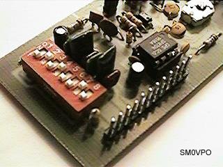
Now that is a bit of a laugh. I have already built loads of these on the same PCB so the use of the term "prototype" is a bit misleading. All functioned well and very close to each-other in specification. Output power of the last six units is about 25% higher than that observed from the first V7, probably because the first one had so much "hacking" around the PCB. Anyway, here is a picture of the final unit.
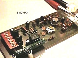
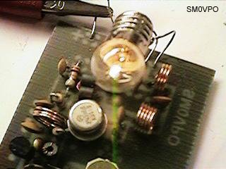
In these two pictures you can see the completed unit, plus a view of the PA stage. At the time of the photograph it was loaded with a 6v 0.1A bicycle lamp and fed with +15v DC supply. The lamp is 600mW lamp at 60 Ohms when fully lit. Here it is lit to well over half brilliance (lowers impedance). This particular unit is delivering +27dBm, according to my Hewlet Packard analyser. I think I am happy with that!
Very best regards from Harry - SM0VPO, Lunda, Sweden.
Return to INFO page